Table of Contents
Advertisement
Quick Links
Advertisement
Table of Contents

Related Manuals for SolarEast BLN-006TB1


Summary of Contents for SolarEast BLN-006TB1
- Page 1 Heat Pump for Heating & Cooling & DHW Service Manual Model: BLN-006TB1、BLN-006TD1 BLN-010TB1、BLN-010TB3 BLN-014TB1、BLN-014TB3 BLN-018TB1、BLN-018TB3 BLN-024TB3、BLN-024TD3 BLN-010TD1、BLN-010TD3 BLN-014TD1、BLN-014TD3 BLN-018TD1、BLN-018TD3 SolarEast Heat Pump Ltd. Service Manual...
-
Page 2: Table Of Contents
1. Product introduction ........................1 1.1. Product model pictures ...................... 1 1.2. Parameter Table ......................... 3 1.3. Dimension .......................... 5 1.3.1. BLN-006TB1、BLN-010TB1、BLN-010TB3 ............. 5 1.3.2. BLN-014TB1、BLN-014TB3 ..................6 1.3.3. BLN-018TB1、BLN-018TB3、BLN-024TB3 ............. 7 1.3.4. BLN-006TD1、BLN-010TD1、BLN-010TD3 ............8 1.3.5. BLN-014TD1、BLN-014TD3 ..................9 1.3.6. - Page 3 P parameter setting table ....................89 3.3. Setting method of pump flow range setting value ............93 3.4. Outdoor unit electric control box layout ................94 3.4.1. BLN-006TB1/ BLN-010TB1/ BLN-014TB1/ BLN-018TB1 ........94 3.4.2. BLN-018TB1 ......................95 3.4.3. BLN-006TB1/ BLN-010TB1/ BLN-014TB1/ BLN-018TB1 ........95 3.4.4.
- Page 4 3.7.13. Floor heating + refrigeration + hot water + gas water circuit wiring diagram... 119 3.7.14. Three-way valve wiring method ................ 120 3.8. Wiring diagram of each model ..................121 3.8.1. BLN-006TB1/ BLN-010TB1/ BLN-014TB1/ BLN-018TB1 electrical schematic diagram ......................... 121 3.8.2. BLN-010TB3/ BLN-014TB3/ BLN-018TB3/ BLN-024TB3 electrical schematic diagram .........................
-
Page 5: Product Introduction
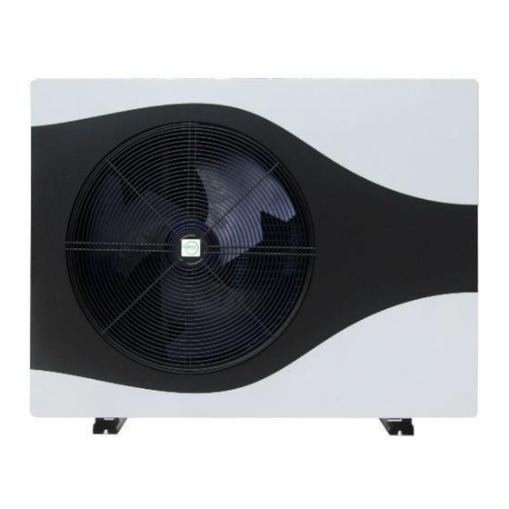
SolarEast Heat Pump Ltd. 2212.A02 1. Product introduction 1.1. Product model pictures BLN-006TB1 BLN-006TB1 BLN-010TB1、BLN-010TB3 BLN-010TB1、BLN-010TB3 Model BLN-014TB1、BLN-014TB3 BLN-014TB1、BLN-014TB3 Picture BLN-018TB1、BLN-018TB3 BLN-018TB1、BLN-018TB3 Model BLN-024TB3 BLN-024TB3 Picture... - Page 6 SolarEast Heat Pump Ltd. 2212.A02 BLN-006TD1 BLN-006TD1 BLN-010TD1、BLN-010TD3 BLN-010TD1、BLN-010TD3 Model BLN-014TD1、BLN-014TD3 BLN-014TD1、BLN-014TD3 Picture BLN-018TD1、BLN-018TD3 Model BLN-024TD3 Picture Table 1-1 Note: TB and TD series are identical in unit capacity and electric control operation except appearance. The following contents are as follows TB Series.
-
Page 7: Parameter Table
SolarEast Heat Pump Ltd. 2212.A02 1.2. Parameter Table Model BLN-006TB1 BLN-010TB1 BLN-010TB3 BLN-014TB1 BLN-014TB3 BLN-018TB1 BLN-018TB3 BLN-024TB3 380- 380- 380- 380- 220-240V 220-240V 220-240V 220-240V Power Supply 415V/3N~/50 415V/3N~/50 415V/3N~/50 415V/3N~/50 ~/50Hz ~/50Hz ~/50Hz ~/50Hz Capacity 2.50-8.30 4.20-12.20 4.20-12.20 5.30-16.50 5.30-16.60... - Page 8 SolarEast Heat Pump Ltd. 2212.A02 Model BLN-006TB1 BLN-010TB1 BLN-010TB3 BLN-014TB1 BLN-014TB3 BLN-018TB1 BLN-018TB3 BLN-024TB3 Maximum Allowable Pressure Electrical Shockproof IP Class IPX4 IPX4 IPX4 IPX4 IPX4 IPX4 IPX4 IPX4 Max. Outlet Water ℃ Temp. Operating Ambient ℃ -25~45 -25~45 -25~45 -25~45...
-
Page 9: Dimension
SolarEast Heat Pump Ltd. 2212.A02 1.3. Dimension 1.3.1. BLN-006TB1、BLN-010TB1、BLN-010TB3 Figure 1-1... -
Page 10: Bln-014Tb1、Bln-014Tb3
SolarEast Heat Pump Ltd. 2212.A02 1.3.2. BLN-014TB1、BLN-014TB3 Figure 1-2... -
Page 11: Bln-018Tb1、Bln-018Tb3、Bln-024Tb3
SolarEast Heat Pump Ltd. 2212.A02 1.3.3. BLN-018TB1、BLN-018TB3、BLN-024TB3 Figure 1-3... -
Page 12: Bln-006Td1、Bln-010Td1、Bln-010Td3
SolarEast Heat Pump Ltd. 2212.A02 1.3.4. BLN-006TD1、BLN-010TD1、BLN-010TD3 Figure 1-4... -
Page 13: Bln-014Td1、Bln-014Td3
SolarEast Heat Pump Ltd. 2212.A02 1.3.5. BLN-014TD1、BLN-014TD3 Figure 1-5... -
Page 14: Bln-018Tb1、Bln-018Tb3、Bln-024Tb3
SolarEast Heat Pump Ltd. 2212.A02 1.3.6. BLN-018TB1、BLN-018TB3、BLN-024TB3 Figure 1-6... -
Page 15: Exploded View
SolarEast Heat Pump Ltd. 2212.A02 1.4. Exploded view 1.4.1. BLN-006TB1、BLN-010TB1、BLN-010TB3、BLN-014TB1、BLN-014TB3 Figure 1-7... -
Page 16: Bln-006Td1、Bln-010Td1、Bln-010Td3、Bln-014Td1、Bln-014Td3
SolarEast Heat Pump Ltd. 2212.A02 1.4.2. BLN-006TD1、BLN-010TD1、BLN-010TD3、BLN-014TD1、BLN-014TD3 Figure 1-8... -
Page 17: Bln-018Tb1、Bln-018Tb3、Bln-024Tb3
SolarEast Heat Pump Ltd. 2212.A02 1.4.3. BLN-018TB1、BLN-018TB3、BLN-024TB3 Figure 1-9... -
Page 18: Bln-018Td1、Bln-018Td3、Bln-024Td3
SolarEast Heat Pump Ltd. 2212.A02 1.4.4. BLN-018TD1、BLN-018TD3、BLN-024TD3 Figure 1-10... -
Page 19: System Diagrams And Performance Curves
SolarEast Heat Pump Ltd. 2212.A02 1.5. System diagrams and performance curves 1.5.1. Schematic diagram of the cooling system Figure 1-11 code Description code Description code Description Compressors Gas-liquid separators Economiser inlet temperature sensor Four-way directional valves DC circulation pumps Economiser outlet temperature sensor... -
Page 20: How Heat Pumps Work
SolarEast Heat Pump Ltd. 2212.A02 Non-standard parts for each model BLN-006TB1 BLN-010TB1/B3 BLN-014TB1/B3 BLN-018TB1/B3 BLN-024TB3 Machine type √ × × × × 10 Throttle solenoid 11 Auxiliary throttling capillary tube × × × × √ 18 Expansion tank × ×... -
Page 21: Introduction To Heat Pump System Components
SolarEast Heat Pump Ltd. 2212.A02 1.5.3. Introduction to Heat Pump System Components Picture Name Function Description The compressor is the heart of the heat pump system. It is a "steam DC inverter pump" that compresses low-temperature and low-pressure vapor into 1... - Page 22 SolarEast Heat Pump Ltd. 2212.A02 Electronic Throttling and pressure-reducing device, throttling medium- expansion temperature and high-pressure liquid refrigerant into low- valve temperature and low-pressure liquid refrigerant Four-way Change the refrigerant flow direction to realize the switching function reversing valve of cooling, heating and defrosting...
- Page 23 SolarEast Heat Pump Ltd. 2212.A02 The expansion tank plays the role of buffering pressure fluctuations Expansion tank and part of the water supply in the water system. The circulating water pump provides power for transporting the heat transfer medium (water) in the heat pump water system, and then...
-
Page 24: Heating Performance Curve
SolarEast Heat Pump Ltd. 2212.A02 1.5.4. Heating Performance Curve Rated Test Conditions: Heating¹: Ambient Temp 7℃/6℃(DB/WB),Water-In/Out Temp 30℃/35℃ Heating²: Ambient Temp 7℃/6℃(DB/WB),Water-In/Out Temp 47℃/55℃ Cooling: Ambient Temp 35℃/24℃(DB/WB),Water-In/Out Temp 12℃/7℃ 1.5.4.1. BLN-006TB1 Figure 1-13... - Page 25 SolarEast Heat Pump Ltd. 2212.A02 1.5.4.2. BLN-010TB1/B3 Figure 1-14...
- Page 26 SolarEast Heat Pump Ltd. 2212.A02 1.5.4.3. BLN-014TB1/B3 Figure 1-15...
- Page 27 SolarEast Heat Pump Ltd. 2212.A02 1.5.4.4. BLN-018TB1/B3 Figure 1-16...
- Page 28 SolarEast Heat Pump Ltd. 2212.A02 1.5.4.5. BLN-024TB3 Figure 1-17...
-
Page 29: Product Selection And Installation
SolarEast Heat Pump Ltd. 2212.A02 2. Product selection and installation 2.1. Product installation instructions and special precautions A. Heat pump cooling and heating and heating water systems should be closed systems. If antifreeze or other refrigerants are used, please consult our company;... -
Page 30: Warning
SolarEast Heat Pump Ltd. 2212.A02 2.1.2. warning 1) Before installation, it should be confirmed that the grid voltage is consistent with the voltage required by the unit, and whether the carrying capacity of the wires and sockets meets the maximum power requirements. -
Page 31: Installation
SolarEast Heat Pump Ltd. 2212.A02 6) If the heat pump unit has not been used for a long time (more than 2 weeks), hydrogen gas may be generated in the hot water piping system, and hydrogen gas is extremely flammable. In this... -
Page 32: Auxiliary Pump Installation
SolarEast Heat Pump Ltd. 2212.A02 electrical devices is 1.0m; When the units are installed adjacent to each other, the distance between the two units should be maintained at 1.0~1.2m, and the base height of the heat pump unit should be more than 0.1m above the ground. -
Page 33: Pipeline Installation; Water Pressure Commissioning; Pipeline Insulation Requirements
SolarEast Heat Pump Ltd. 2212.A02 calculated according to the pipeline and the coil of the heat storage tank. Installation position: Auxiliary water pump Pc circulates the water inlet pipe in the hot water tank, and accesses the control signal from the unit. - Page 34 SolarEast Heat Pump Ltd. 2212.A02 collectors and distributors in the smallest area is less than or equal to 2, install a differential pressure bypass valve according to the schematic diagram; (9) If the unit does not operate in winter, the water inside the system must be drained to prevent freezing of pipelines or components.
-
Page 35: Precautions For Electrical Wiring
SolarEast Heat Pump Ltd. 2212.A02 2.3.1.5. Water pressure commissioning and water pressure test shall meet the following requirements (1) Before the test, the pipeline should be fixed, the joints should be exposed, and the water distribution equipment should not be connected;... - Page 36 SolarEast Heat Pump Ltd. 2212.A02 effective. (3) The user's incoming power supply must be installed with a leakage protection device. (4) The wiring construction must be connected by professional installation technicians according to the circuit diagram. (5) The power lines and signal lines should be neatly and reasonably arranged without interfering with each other.
- Page 37 SolarEast Heat Pump Ltd. 2212.A02 Electrical specification recommendation BLN-006 BLN-010 BLN-010 BLN-014 BLN-014 BLN-018 BLN-018 BLN-024 model Power supply 400V/3N~ 400V/3N~ 400V/3N~ 400V/3N~ 230V/50Hz 230V/50Hz 230V/50Hz 230V/50Hz V/Hz 50Hz 50Hz 50Hz 50Hz Maximum power 2.71 3.83 3.83 6.20 6.20 7.50 7.50...
-
Page 38: Room Heat Load Calculation
SolarEast Heat Pump Ltd. 2212.A02 2.5. Room heat load calculation 2.5.1. basic requirements The heat load of the heating system in winter shall be determined according to the following heat loss and gain of the building: 1) Heat consumption of the enclosure structure;... - Page 39 SolarEast Heat Pump Ltd. 2212.A02 When the floor radiation is used for local area heating of the room and other areas are not heated, the heat dissipation required for floor radiation can be determined by multiplying the heat dissipation required for overall radiant heating by the calculation coefficient in Table 1-2 ‘Calculation Coefficients of Heat Consumption...
-
Page 40: Water System Design
SolarEast Heat Pump Ltd. 2212.A02 local average surface temperature is too high, the following measures can be taken: Improve the thermal performance of the building envelope; Add other heating equipment; Under the condition of satisfying the comfort level, reduce the indoor calculated temperature appropriately. -
Page 41: Selection Of Floor Heating Heat Pump Unit
SolarEast Heat Pump Ltd. 2212.A02 When there is a large difference in the length of each loop, it is advisable to use heating pipes with different diameters, or set a balance device on each branch loop. 2.5.4. Selection of floor heating heat pump unit (1) Calculate the design heat load of the room Room design heat load = additional coefficient ×... - Page 42 SolarEast Heat Pump Ltd. 2212.A02 pump should be added. 3) Select the most unfavorable water system loop, carry out hydraulic calculation, and select the circulating water pump according to the total pressure head loss and considering the margin. B. Pump head Calculate the resistance loss of the ground heating buried pipe and select the head of the water pump.
- Page 43 SolarEast Heat Pump Ltd. 2212.A02 Expansion tank specifications Volume (L) Preset pressure(bar) 1.5~3 1.5~3 1.5~3 1.5~3 1.5~3 1.5~3 1.5~3 1.5~3 Maximum pressure (bar) Interface diameter 3/4〞 3/4〞 3/4〞 3/4〞 3/4〞 3/4〞 3/4〞 3/4〞 Maximum working temperature (℃) Table 2-6 Calculation selection:...
- Page 44 SolarEast Heat Pump Ltd. 2212.A02 Figure 2-3 E. filter The water return port of the heat pump unit must be equipped with a water filter, which can reduce impurities in the pipeline from entering the filter and protect the normal energy-saving operation of the unit.
- Page 45 SolarEast Heat Pump Ltd. 2212.A02 system pressure exceeds the specified value, the safety valve opens to discharge part of the hot water in the system, so that the system pressure does not exceed the allowable value, so as to ensure that the system will not cause accidents due to excessive pressure.
- Page 46 SolarEast Heat Pump Ltd. 2212.A02 Connection size 1/2″MF 1/2″FF 3/4″M1/2″F 3/4″M1/2″M Maximum water inlet pressure (bar) Pressure adjustment range (bar) 0.3~3 0.3~3 0.3~3 0.3~3 Factory preset pressure (bar) Table 2-9 Suggestion for model selection: The pressure setting of the automatic replenishment valve is 0.3 bar higher than the static pressure, but the set value must be lower than the replenishment pressure (water inlet pressure), otherwise the water cannot be replenished normally.
- Page 47 SolarEast Heat Pump Ltd. 2212.A02 fluctuation of the water system. The buffer water tank adopts the pressure-bearing type, the maximum working pressure is ≥7bar, and the size of the nozzle is in accordance with the size of the main pipe.
- Page 48 SolarEast Heat Pump Ltd. 2212.A02 C----- The specific heat of water is taken as 4.2 (kJ / (kg·℃) ) V------- water tank volume, unit L L. Type selection of inner coil of hot water tank Household hot water is usually heated by built-in coils, so the specification selection of the inner coils directly affects the heating effect and unit operation reliability.
- Page 49 SolarEast Heat Pump Ltd. 2212.A02 Figure 2-5: water pump connection diagram Type selection: rated current of circuit breaker (C/D series) ≈1.2* rated current of water pump Copper core power cord: choose 1.5mm2 below 5A 5A~12A choose 2.5mm2 12A~20A choose 4mm2 N.
- Page 50 SolarEast Heat Pump Ltd. 2212.A02 mg/L ≤150 generally ≤0.5 total iron aluminum equipment ≤0.1 generally ≤0.5 total copper aluminum equipment ≤0.02 Table 2-13 a. During the operation of the heat pump unit, the water quality needs to be sampled and analyzed regularly (suggested every six months).
-
Page 51: Waterway Antifreeze Protection
SolarEast Heat Pump Ltd. 2212.A02 2.6. *Waterway antifreeze protection Freezing can damage the circulatory system. Since outdoor units may be exposed to sub-zero temperatures, care must be taken to prevent the system from freezing. All internal fluid circulation parts are insulated to reduce heat loss. -
Page 52: Electrical Operation
SolarEast Heat Pump Ltd. 2212.A02 3. Electrical operation 3.1. Control 3.1.1. out of service The outage occurs for the following reasons: (1) Abnormal shutdown: In order to protect the compressor, if there is an abnormal state, the controller interface will display the system error code. - Page 53 SolarEast Heat Pump Ltd. 2212.A02 judge as follows: Unit inlet water temperature T8<heating set temperature - return difference [P26] or [P27], if there is capacity demand, the unit must be started; When the parameter [P37]=0, the unit inlet water temperature T8≥heating set temperature, and the compressor is at the lowest frequency and continues to run for ≥5min, the unit reaches the temperature and...
- Page 54 SolarEast Heat Pump Ltd. 2212.A02 increases "outlet water temperature T15>refrigeration set temperature + hysteresis temperature + ΔT, ΔT=the difference before shutdown (absolute value), and the outlet water temperature T15>5°C” and other controls are the same. When P26 and P27 are set to 0, hysteresis temperature = 5-X/10, X = inlet water temperature T8, range value 2 ≤...
-
Page 55: High Temperature Sterilization
SolarEast Heat Pump Ltd. 2212.A02 When parameter【P37】=2, cooling is controlled according to parameter【P37】=0, and floor heating is controlled according to parameter【P37】=1. Note: When parameter P116=1, the unit is controlled by the outlet water temperature T15; when parameter P116=1, the unit is controlled by the inlet water temperature T8. -
Page 56: Linkage Control
SolarEast Heat Pump Ltd. 2212.A02 3.1.8. Linkage control (1) When P05=1, the linkage switch DI6 is disabled, and the unit starts and stops according to the normal control of the wire controller: (2) When P05=0, if the linkage switch DI6 is off, the unit is not allowed to start; if the linkage switch DI6 is on, it will start and stop according to the water temperature;... -
Page 57: Heating Auxiliary Electric Heater Eh2
SolarEast Heat Pump Ltd. 2212.A02 1) When the outdoor ambient temperature T7 ≥ the set ambient temperature of hot water electric heating + 3°C, this item is invalid when the outdoor ambient temperature T7 sensor fails; 2) Hot water tank temperature T16 ≥ set temperature. -
Page 58: Unit Auxiliary Pump P_C
SolarEast Heat Pump Ltd. 2212.A02 C. When the unit is not anti-freezing, when it is turned off or turned on for cooling, the heating auxiliary electric heater EH2 stops. D. When the unit is in the heating or floor heating mode, follow the following controls:... -
Page 59: Air Conditioner Secondary Water Pump P_B (Secondary System)
SolarEast Heat Pump Ltd. 2212.A02 mode. 3.1.16. Air conditioner secondary water pump P_b (secondary system) A. When P150=1 is selected: the unit will start running when there is a start signal or when the unit reaches temperature and is on standby;... -
Page 60: Heat Source Heating Water Pump P_F
SolarEast Heat Pump Ltd. 2212.A02 (3) When the heat source linkage switch DI6 is closed; If the above conditions are met at the same time, the heat source water pump is turned on. Closing condition: (1) When it is detected that the temperature of the heat source on the hot water side T12≤the... - Page 61 SolarEast Heat Pump Ltd. 2212.A02 default 2 minutes), and each waterway runs for 2 minutes; 2) When the outdoor ambient temperature T7≥ [P117] +3℃, exit the first-level antifreeze protection; (2) Entry and exit of secondary antifreeze protection 1) When the outdoor ambient temperature T7≤5℃ ]P117] and the outlet water temperature T15≤3℃...
-
Page 62: Host Water Flow Switch Protection
SolarEast Heat Pump Ltd. 2212.A02 3.1.20. Host water flow switch protection A. When P101=0, that is, when the AC water pump is selected, it is detected in the following way: (1) After the main engine water pump P_a starts running for 40 seconds, if the water flow switch is disconnected for 5 consecutive seconds, it will enter the water flow switch protection, the compressor and water pump will stop running immediately, and the fault code "E03"... -
Page 63: Protection Against Excessive Temperature Difference Between Inlet And Outlet Pipes
SolarEast Heat Pump Ltd. 2212.A02 3.1.21. Protection against excessive temperature difference between inlet and outlet pipes (1) After the compressor starts running for 3 minutes, it is detected that the outlet water temperature T15-inlet water temperature T8≥ temperature difference protection value (parameter P23) or the inlet water temperature T8-outlet water temperature T15≥... -
Page 64: Display And Operation Of The Wire Controller
SolarEast Heat Pump Ltd. 2212.A02 3.2. Display and operation of the wire controller 3.2.1. Wire controller interface display and operation... - Page 65 SolarEast Heat Pump Ltd. 2212.A02...
- Page 66 SolarEast Heat Pump Ltd. 2212.A02...
- Page 67 SolarEast Heat Pump Ltd. 2212.A02...
-
Page 68: Setting And Operation Of Climate Temperature Curve
SolarEast Heat Pump Ltd. 2212.A02 3.2.2. Setting and operation of climate temperature curve... - Page 69 SolarEast Heat Pump Ltd. 2212.A02...
-
Page 70: Setting And Operation Of Unit Tooling Number
2212.A02 3.2.3. Setting and operation of unit tooling number The model tooling number correspondence table is as follows: Model tooling number comparison table BLN-006TB1 BLN-010TB1/3 BLN-014TB1/3 BLN-018TB1/3 BLN-024TB1/3 Model tooling number Table3-1 Each model has a unique tooling number, which determines the factory default parameters of the modified model. -
Page 71: Network Connection Method And Display Of Multiple Units
SolarEast Heat Pump Ltd. 2212.A02 3.2.4. Network connection method and display of multiple units... -
Page 72: Operation Method Of Unit Status Parameter Query
SolarEast Heat Pump Ltd. 2212.A02 When using modular control, please be sure to check the device address before powering on the unit. The master group number is "0", the 1# slave address is "1", the 2# slave address is "2", and so on. Please refer to the... - Page 73 SolarEast Heat Pump Ltd. 2212.A02 State parameter table code representative meaning display range code representative meaning display range Compressor operating frequency 0~150Hz reserve Fan operating frequency/speed 0~999Hz reserve 0~480P Electronic expansion valve steps reserve EVI valve steps 0~480P reserve AC input voltage 0~500V...
-
Page 74: Factory Parameter Setting Method
SolarEast Heat Pump Ltd. 2212.A02 3.2.6. Factory parameter setting method 3.2.6.1. Single unit parameter setting 3.2.6.2. Parameter settings in master-slave cascade mode In the state of setting parameters, switch the master and slave through the clock key and M key:... - Page 75 SolarEast Heat Pump Ltd. 2212.A02 3.2.6.3. When the air conditioner secondary water pump P_b temperature control P150=3, the temperature setting operation For more detailed control functions, please refer to [3.1.16 Air Conditioning Secondary Water Pump P_b]. 3.2.6.4. Enable and disable settings for hot water mode, high temperature sterilization, and...
-
Page 76: Reset
SolarEast Heat Pump Ltd. 2212.A02 (2) Enabling and disabling of high temperature sterilization function (L12): Sterilization function selection: 【L12】=0, automatic; 【L12】=1, disabled; 【L12】=2, manual. For more detailed control functions, please refer to【3.1.4 High Temperature Sterilization】. (3) Manually start the high-temperature sterilization function forcibly (when P140=0 and L12≠1) -
Page 77: Touch Screen Controller Operation
SolarEast Heat Pump Ltd. 2212.A02 3.2.8. *Touch screen controller operation 3.2.8.1. Wired controller LCD display (1) Power-on display As shown in the figure below, select the corresponding language option and click " " to enter the system. If you do not select a language for more than 2 minutes, you will automatically enter the system according to the currently selected language, and the screen will be closed. - Page 78 SolarEast Heat Pump Ltd. 2212.A02 (2) main interface display (3) Icon Description The top of the main interface displays from left to right: time, day-month-year, week, defrost, cascade, mute, water pump, return valve, electric heating, compressor, fan, WIFI. Defrost display: When the unit enters defrost, "...
- Page 79 SolarEast Heat Pump Ltd. 2212.A02 Fault display: When there is a unit fault, " " flashes, click this icon to enter the real-time fault/fault record. When the fault is eliminated, the icon will go out; click the icon to enter the fault query page; up to 20 real-time faults and 50 historical faults can be displayed.
- Page 80 SolarEast Heat Pump Ltd. 2212.A02 (4) Temperature setting A. Single mode (heating, cooling, floor heating, hot water) ① Click "+" "-" to adjust the set temperature of the current mode. ② Sliding the slider bar can also set the setting temperature of the current mode.
- Page 81 SolarEast Heat Pump Ltd. 2212.A02 3.2.8.2. Remote control operation (1) Power button In the bright screen state, click the power button " " to realize the power on/off operation. When starting up, ON is displayed below the icon, and the current mode is displayed in the upper left corner.
- Page 82 SolarEast Heat Pump Ltd. 2212.A02 (1) User command operation When the main interface is on, click the " " button to enter the function selection page. Then click " " to enter the user command operation. From top to bottom, they are silent mode, high temperature sterilization, forced defrosting, manual quick heating, and system emptying.
- Page 83 SolarEast Heat Pump Ltd. 2212.A02 (3) WiFi distribution network In the bright screen state, click the " " button to enter the function selection page. Click " " to enter the WIFI operation interface. Long press the button for more than 3S and release it to enter the corresponding WIFi distribution network mode, and the corresponding button lights up.
- Page 84 SolarEast Heat Pump Ltd. 2212.A02 (5) Factory function Inverter experiment test: In the bright screen state, click the " " button to enter the function selection page. Then click" ". Input "1122" on the pop-up keyboard and press "Enter" to enter the factory function.
- Page 85 SolarEast Heat Pump Ltd. 2212.A02 (7) Scene setting In the bright screen state, click the " " button to enter the function selection page. Click " " to enter the scene setting interface. A total of 6 scene settings per day can be set for daily timing or weekly cycle timing. Click "...
- Page 86 SolarEast Heat Pump Ltd. 2212.A02 (1) User parameter query Set temperature, hysteresis, return water temperature, anti-virus. In the bright screen state, press “ ” to enter the query page, and then click “ ” to enter the user parameter list, the modification method refers to the factory parameter setting.
- Page 87 SolarEast Heat Pump Ltd. 2212.A02 (4) Power module parameter query (optional) When the machine is equipped with a power module, press " " to enter the query page when the screen is on. Click “ ” to enter the power consumption information query of the unit, and you can query the total power consumption, current power, voltage, and current parameters.
- Page 88 SolarEast Heat Pump Ltd. 2212.A02 3.2.8.5. Setting menu (1) Clock setting When the screen is on, press " " to enter the setting page. Click " " to enter the time setting page. Click the corresponding year, month, and day to enter the value through the keyboard, and finally press...
- Page 89 SolarEast Heat Pump Ltd. 2212.A02 (2) R/C Brightness and Language Settings When the screen is on, press " " to enter the setting page, then click " " to enter the brightness setting interface, slide the slider to set different brightness. Click "...
- Page 90 SolarEast Heat Pump Ltd. 2212.A02 At this time, you can press " "and" "to turn the page to view the value of each parameter, and click the parameter to be modified to enter the parameter modification page. On this page, the parameter number, current parameter value, setting value, and setting range can be displayed.
- Page 91 SolarEast Heat Pump Ltd. 2212.A02 (5) View the program version When the screen is on, press " " to enter the setting page, and then click " " to view the program version numbers of the display and mainboard.
-
Page 92: L Parameter Setting Table
SolarEast Heat Pump Ltd. 2212.A02 L parameter setting table Factory Parameter Description range Note parameters Compressor manual control 0 automatic, 1 manual 0~1 Compressor target frequency 0~120Hz Fan manual control 0 automatic, 1 manual 0~1 0-70Hz (when PO6 chooses 1) Fan target frequency 0~70... -
Page 93: P Parameter Setting Table
SolarEast Heat Pump Ltd. 2212.A02 Table3-4 P parameter setting table Parameter Description Note range reserve 0~1 High voltage switch setting 0 enables, 1 disables 0~1 Low pressure switch setting 0 enables, 1 disables 0~1 Water flow switch setting 0 enables, 1 disables 0~1... - Page 94 SolarEast Heat Pump Ltd. 2212.A02 Air conditioning return difference (host) 0~10℃ Floor heating return difference (host) 0~10℃ Water pump control (host) when the 0 running/1 stop/2 cooling running/3 air 0~4 temperature reaches the shutdown conditioning running/4 floor heating running Antifreeze water pump running time (every 0~10min...
- Page 95 SolarEast Heat Pump Ltd. 2212.A02 Quiet Mode Compressor Frequency 20-70Hz Quiet Mode Fan Frequency Speed = frequency * 15 20-60Hz Network pump operation mode 0: shared, 1: independent Hot water return difference (host) 0~10℃ Water pump speed regulation temperature 2~10℃...
- Page 96 SolarEast Heat Pump Ltd. 2212.A02 Defrosting dew point constant P142 ℃ Defrost can enter the water temperature P143 ℃ Defrost can enter ambient temperature P144 -20~30 Outlet water antifreeze protection value antifreeze probe P145 -30~10 Set the maximum range value...
-
Page 97: Setting Method Of Pump Flow Range Setting Value
SolarEast Heat Pump Ltd. 2212.A02 3.3. Setting method of pump flow range setting value The parameter setting value of P146 determines whether the feedback flow value of the 25 state parameters is accurate. Different pump models have corresponding setting values. See the table below for... -
Page 98: Outdoor Unit Electric Control Box Layout
GPA25-11H BLN-014TB1/3 BLN-024TB3 BLN-006TB1 BLN-010TB1/3 BLN-014TB1/3 Table3-8 3.4. Outdoor unit electric control box layout 3.4.1. BLN-006TB1/ BLN-010TB1/ BLN-014TB1/ BLN-018TB1 AP4: Switching power supply board PCB AP3: water pump expansion board PCB AP1: main control board PCB AP2: Driver board PCB... -
Page 99: Bln-018Tb1
SolarEast Heat Pump Ltd. 2212.A02 3.4.2. BLN-018TB1 AP4: Switching power supply board PCB AP1: main control board PCB AP2: Compressor driver board PCB AP3: water pump expansion board PCB 3.4.3. BLN-006TB1/ BLN-010TB1/ BLN-014TB1/ BLN-018TB1 XT1 power input 230VAC 15-20:DC12V 1-14:220VAC... -
Page 100: Bln-010Tb3/ Bln-014Tb3
SolarEast Heat Pump Ltd. 2212.A02 3.4.4. BLN-010TB3/ BLN-014TB3 AP2: Switching power supply board PCB AP1: main control board AP2: Compressor driver board AP5: Fan Power Board PCB AP3: Water Pump Expansion Board 3.4.5. BLN-018TB3 AP2: Switching power supply board PCB... -
Page 101: Bln-024Tb3
SolarEast Heat Pump Ltd. 2212.A02 3.4.6. BLN-024TB3 AP3: water pump expansion board PCB AP3: water pump expansion board PCB AP2: Compressor Driver Board PCB AP1: main control board PCB AP5: Fan Power Board PCB 3.4.7. BLN-010TB3/ BLN-014TB3/ BLN-018TB3/ BLN-024TB3 XT1 power input 400VAC 1-14:230VAC... -
Page 102: Host Unit Port Definition Diagram
SolarEast Heat Pump Ltd. 2212.A02 3.5. Host unit port definition diagram 3.5.1. Main control board port definition diagram (AP1) port Description port Description port Description Hot water electric Flow switch low pressure sensor heating/gas signal output Four-way valve low voltage switch... -
Page 103: Port Definition Diagram Of Water Pump Expansion Board (Ap3)
SolarEast Heat Pump Ltd. 2212.A02 reserve Power input S phase Host linkage switch Power input R phase Table3-9 3.5.2. Port Definition Diagram of Water Pump Expansion Board (AP3) port Description port Description Heating secondary circulation pump linkage OUT1 Circulating pump... - Page 104 SolarEast Heat Pump Ltd. 2212.A02 Spare motherboard port Description port Description OUT1 Circulating pump reserve P_b: heating secondary circulation OUT2 reserve pump Heating secondary circulation pump OUT3 SV1: Air conditioner valve closed linkage switch Heat source heating side linkage OUT4...
-
Page 105: Port Definition Diagram Of Switching Power Supply (Ap4)
SolarEast Heat Pump Ltd. 2212.A02 3.5.3. Port definition diagram of switching power supply (AP4) Fuse 3.15A/250VAC Secondary 1 DC12V Power input 230VAC Secondary 2 DC12V 3.5.4. DC fan board port definition diagram (AP5) 2# DC fan DC310V 1# DC fan DC310V... - Page 106 SolarEast Heat Pump Ltd. 2212.A02 (2) For BLN-014/TB1, BLN-018/TB1 Compressor connection port V Compressor connection port U 230VAC power input L Compressor connection 230VAC power port W input N Ground PE RS485 communication 2# DC fan 1# DC fan interface...
-
Page 107: Fault Code And Fault Reason
SolarEast Heat Pump Ltd. 2212.A02 AP1 main control board - temperature sensor T9/T10/T11/T12/T16 (enable and disable): Optional external probe: (1) T9 total outlet water temperature is enabled, dial 7=ON (not enabled by default) (2) T10 heating water tank temperature is enabled, dial 6=ON (not enabled by default) - Page 108 SolarEast Heat Pump Ltd. 2212.A02 1. Whether the pressure switch is damaged and whether the wiring is correct 2. Lack of refrigerant in the system E 06 Low voltage switch failure 3. Is the fan working normally? 4. There is blockage in the fluorine system...
- Page 109 SolarEast Heat Pump Ltd. 2212.A02 1. The sensor cable is disconnected or short-circuited Fluorine circuit antifreeze temperature E 24 2. The sensor is damaged failure (fluorine circuit) 3. The motherboard port is damaged E 25 reserve reserve 1. The sensor cable is disconnected or short-circuited...
- Page 110 SolarEast Heat Pump Ltd. 2212.A02 2. The sensor is damaged 3. The motherboard port is damaged 1. The sensor cable is disconnected or short-circuited E 48 Economizer inlet sensor failure 2. The sensor is damaged 3. The motherboard port is damaged...
- Page 111 SolarEast Heat Pump Ltd. 2212.A02 3. The motherboard port is damaged 1. The sensor cable is disconnected or short-circuited E A4 Heating water tank sensor failure 2. The sensor is damaged 3. The motherboard port is damaged 1. The sensor cable is disconnected or short-circuited...
- Page 112 SolarEast Heat Pump Ltd. 2212.A02 P27 NA P28 NA P29 NA P30 NA P31 NA P32 NA P33 IPM Module Thermal Shutdown P34 Compressor phase loss P35 compressor overload P36 Input Current Sampling Fault P37 IPM supply voltage failure P38 Precharge Circuit Voltage Failure...
-
Page 113: Waterway Installation And Wiring
SolarEast Heat Pump Ltd. 2212.A02 3.7. Waterway installation and wiring 3.7.1. Comparison of system legends Legend code comparison table Code assembly unit Code assembly unit Auxiliary heat source water pump P_e linkage switch Heat pump host on the heating side... -
Page 114: Single Floor Heating Mode Water System Installation Diagram
SolarEast Heat Pump Ltd. 2212.A02 3.7.2. Single floor heating mode water system installation diagram 3.7.3. Heating or cooling mode water system installation diagram When the application scenario is underfloor heating, heating, and cooling mode, it is necessary to set parameters P48=0 (disable the water tank temperature sensor), L12=1 (disable high-temperature sterilization). -
Page 115: Schematic Diagram Of Wiring In Floor Heating, Heating, And Cooling Modes
SolarEast Heat Pump Ltd. 2212.A02 3.7.4. Schematic diagram of wiring in floor heating, heating, and cooling modes... -
Page 116: Hot Water + Cooling Or Hot Water + Heating Mode Water System Installation Diagram
SolarEast Heat Pump Ltd. 2212.A02 3.7.5. Hot water + cooling or hot water + heating mode water system installation diagram 3.7.6. Hot water + floor heating mode water system installation diagram (1) When the lift of the DC water pump of the unit P_a pump is not enough, the auxiliary water pump P_c needs to be connected externally, and the parameter P161 needs to be set to 0 . -
Page 117: Water Wiring Diagram For Hot Water + Cooling, Hot Water + Heating, Hot Water + Floor Heating Modes
SolarEast Heat Pump Ltd. 2212.A02 3.7.7. Water wiring diagram for hot water + cooling, hot water + heating, hot water + floor heating modes... -
Page 118: Mixed Mode Waterway System Installation Diagram
SolarEast Heat Pump Ltd. 2212.A02 3.7.8. Mixed mode waterway system installation diagram... -
Page 119: Wiring Diagram In Hybrid Mode
SolarEast Heat Pump Ltd. 2212.A02 3.7.9. Wiring diagram in hybrid mode... -
Page 120: Cascade Mode Waterway Installation Schematic
SolarEast Heat Pump Ltd. 2212.A02 3.7.10. Cascade mode waterway installation schematic T9 total outlet water temperature is disabled by factory default. In the cascading mode of multiple units, it must be enabled through the dial switch 7, otherwise the unit will not operate normally. -
Page 121: Cascading Mode Water Circuit Wiring Diagram
SolarEast Heat Pump Ltd. 2212.A02 3.7.11. Cascading mode water circuit wiring diagram... -
Page 122: Floor Heating + Refrigeration + Hot Water + Gas Waterway Installation Schematic
SolarEast Heat Pump Ltd. 2212.A02 3.7.12. Floor heating + refrigeration + hot water + gas waterway installation schematic Note: When parameter P139-2 and P140=2 enable AHS gas control, the hot water electric heating signal becomes AHS gas control signal output. (Program version above 3.67 is valid). -
Page 123: Floor Heating + Refrigeration + Hot Water + Gas Water Circuit Wiring Diagram
SolarEast Heat Pump Ltd. 2212.A02 3.7.13. Floor heating + refrigeration + hot water + gas water circuit wiring diagram... -
Page 124: Three-Way Valve Wiring Method
SolarEast Heat Pump Ltd. 2212.A02 3.7.14. Three-way valve wiring method (1) Three-wire one-control three-way valve wiring method: According to the above figure, C is the input terminal, and the output terminals are A and B. When the voltage (VAC230V) is only applied to the L line, the valve maintains the initial position C-B, that is, the flow drops from C to B position. -
Page 125: Wiring Diagram Of Each Model
SolarEast Heat Pump Ltd. 2212.A02 3.8. Wiring diagram of each model 3.8.1. BLN-006TB1/ BLN-010TB1/ BLN-014TB1/ BLN-018TB1 electrical schematic diagram... -
Page 126: Bln-010Tb3/ Bln-014Tb3/ Bln-018Tb3/ Bln-024Tb3 Electrical Schematic Diagram
SolarEast Heat Pump Ltd. 2212.A02 3.8.2. BLN-010TB3/ BLN-014TB3/ BLN-018TB3/ BLN-024TB3 electrical schematic diagram... -
Page 127: Nct Sensor Resistance Table
SolarEast Heat Pump Ltd. 2212.A02 3.9. NCT Sensor Resistance Table 5K Sensor Resistance Table temperature Resistance temperature Resistance temperature Resistance temperature Resistance temperature Resistance temperature Resistance temperature Resistance (℃) (KΩ) (℃) (KΩ) (℃) (KΩ) (℃) (KΩ) (℃) (KΩ) (℃) (KΩ) (℃) - Page 128 SolarEast Heat Pump Ltd. 2212.A02 50K Sensor Resistance Table temperature Resistance temperature Resistance temperature Resistance temperature Resistance temperature Resistance temperature Resistance temperature Resistance (KΩ) (KΩ) (KΩ) (KΩ) (KΩ) (KΩ) (KΩ) (℃) (℃) (℃) (℃) (℃) (℃) (℃) 1588 306.29 75.001 22.648...
-
Page 129: Error Diagnosis And Treatment
SolarEast Heat Pump Ltd. 2212.A02 4. Error Diagnosis and Treatment 4.1. maintenance tools tool name Picture Function Phillips Remove Phillips 1 screwdriver screws (6 inches) Slotted Remove the flat 2 screwdriver screw (6 inches) Adjustable Screw removal, 3 wrench (6 etc. - Page 130 SolarEast Heat Pump Ltd. 2212.A02 Measure current, clamp voltage, multimeter resistance, capacitance, etc. vacuum Fluorine system pump vacuuming Measurement of Double head fluorine system pressure pressure, gauge vacuuming, etc. Note: Other special tools are not listed, and the above tools can guarantee basic...
-
Page 131: Model Disassembly And Parts
SolarEast Heat Pump Ltd. 2212.A02 4.2. Model disassembly and parts Picture steps How to remove the front trim panel: Use a "+" type 1 screwdriver or electric cross tool to unscrew the 7 screws on the front panel. Remove the front trim panel to 2... - Page 132 SolarEast Heat Pump Ltd. 2212.A02 Open the top cover 4 upwards Right side panel removal: After the top cover is removed, you only need to remove the two fixing screws under 5 the right side panel, and you can press down to remove the right side panel.
- Page 133 SolarEast Heat Pump Ltd. 2212.A02 Front panel removal: Use a "+"-shaped screwdriver or an electric cross tool 6 to remove the 7 screws on the front, the 2 screws on the fan fixing plate, and the screws on the left...
- Page 134 SolarEast Heat Pump Ltd. 2212.A02 Fan blade removal: Hold the nut with an adjustable wrench and turn the wrench clockwise. Motor removal: Use a "+"-shaped screwdriver or an electric cross tool to remove the four fixing screws. Rear trim panel removal: Use a "+"-shaped...
- Page 135 SolarEast Heat Pump Ltd. 2212.A02 Backplane removal: Use a "+"-shaped screwdriver or electric cross tool to pull out the drainage buckle, remove the back panel, and remove the fixing screws. Removal of the top cover of the electrical box: Use a "+"-shaped...
- Page 136 SolarEast Heat Pump Ltd. 2212.A02 Reactor removal: Use a "+"-shaped screwdriver or an electric cross tool to remove the reactors I2 and I1.
- Page 137 SolarEast Heat Pump Ltd. 2212.A02 15kW main circuit electronic expansion valve removal: Main circuit electronic expansion valve EXV1 15kW auxiliary circuit electronic expansion valve removal: Auxiliary electronic expansion valve EXV2...
- Page 138 SolarEast Heat Pump Ltd. 2212.A02 15kW fan High pressure sensor A14 (red)
- Page 139 SolarEast Heat Pump Ltd. 2212.A02 15kW low pressure sensor: Low pressure sensor A13 (blue) 15kW high voltage switch: High voltage switch...
- Page 140 SolarEast Heat Pump Ltd. 2212.A02 15kW low voltage switch: Low voltage switch 15kW ambient temperature sensor: Ambient temperature sensor T7 (5K)
- Page 141 SolarEast Heat Pump Ltd. 2212.A02 15kW inlet water temperature sensor: Inlet water temperature sensor T8 (5K) 15kW outlet water temperature sensor: Outlet water temperature sensor T15 (5K)
- Page 142 SolarEast Heat Pump Ltd. 2212.A02 15kW water tank temperature temperature sensor T16 (5K) 15kW economical inlet temperature sensor T5 (5K)
- Page 143 SolarEast Heat Pump Ltd. 2212.A02 15kW economic output temperature sensor: Economic temperature sensor T6 (5K) 15kW coil temperature sensor: Coil temperature sensor T2...
- Page 144 SolarEast Heat Pump Ltd. 2212.A02 15kW return air temperature sensor: Return air temperature sensor T2 (5K) 15kW exhaust gas temperature sensor: Exhaust gas temperature sensor 50K...
- Page 145 SolarEast Heat Pump Ltd. 2212.A02 15kW inner disk temperature sensor: Inner plate temperature sensor T4 (5K) 15kW wire controller 15kw water flow switch: Water flow switch 15kw four-way valve: Four-way valve...
- Page 146 SolarEast Heat Pump Ltd. 2212.A02 15kw circulating water pump: Circulating water pump OUT1 Compressor heating cable 15kw compressor...
-
Page 147: Troubleshooting And Maintenance Of Common Fault Codes
SolarEast Heat Pump Ltd. 2212.A02 4.3. Troubleshooting and maintenance of common fault codes Maintenance method: R, S, T three live wires can be E01: wrong exchanged for any phase two (after the protection exchange, power on again). (220v machines will not have this failure.) - Page 148 SolarEast Heat Pump Ltd. 2212.A02 Maintenance method: Step 1: Check whether the pipeline valve is fully open. (Make sure the water flow is clear.) Step 2: Check E03: water whether the water flow switch flow switch is failure or installed backwards...
- Page 149 SolarEast Heat Pump Ltd. 2212.A02 reversed. Step 1: Check whether the high- pressure pressure E05: High switch is damaged voltage and whether the switch wiring terminals are failure correct. (High voltage switch D11 red) Step 2: Use a pressure gauge to...
- Page 150 SolarEast Heat Pump Ltd. 2212.A02 Step 3: Check the system for blockage or air in the system. Use a pressure gauge to connect E05: High the high and low voltage pressure inspection switch ports at the same failure time to measure...
- Page 151 SolarEast Heat Pump Ltd. 2212.A02 Step 6: Check whether the fouling of the water side heat exchanger is serious. (In areas E05: High with poor water voltage quality, oxalic acid switch and citric acid failure should be used to clean the inside of...
- Page 152 SolarEast Heat Pump Ltd. 2212.A02 refrigerant, use foam to check whether there is refrigerant leakage at the welding joint of the copper pipe.) E06: Low Step 3: Check voltage whether the fan is switch operating normally. failure Step 4: Check the system for blockage.
- Page 153 SolarEast Heat Pump Ltd. 2212.A02 1: Check whether E09: the communication Communic between the wire ation controller and the failure main board is between normal. the wire 2: Use a multimeter controller to measure and the whether the voltage main...
- Page 154 SolarEast Heat Pump Ltd. 2212.A02 Step 2: Check whether the exhaust gas E12: temperature sensor Exhaust is damaged and use temperatu a multimeter to re too high measure whether protection the resistance value is correct (T3 red port). 1: The sensor...
- Page 155 SolarEast Heat Pump Ltd. 2212.A02 1: The sensor connection line is open or disconnected. E15: Inlet 2: The sensor is water damaged. temperatu 3: The motherboard re sensor port is damaged. failure 4: Use a multimeter to measure whether the resistance is correct (T8 white port).
- Page 156 SolarEast Heat Pump Ltd. 2212.A02 1: The sensor connection line is open or disconnected. 2: The sensor is E18: damaged. Exhaust 3: The motherboard sensor port is damaged. failure 4: Use a multimeter to measure whether the resistance is correct (TI red port).
- Page 157 SolarEast Heat Pump Ltd. 2212.A02 1: The sensor cable is disconnected or E34: Low open. pressure 2: Sensor failure. sensor 3: The motherboard failure port is damaged (D12 blue port). Step 1: Check whether the pipeline valve is fully open.
-
Page 158: Schedule
SolarEast Heat Pump Ltd. 2212.A02 Schedule Schedule A: Unit Ground Heat Dissipation and Ground-to-Soil Heat Loss (1) Heat dissipation per unit ground area of PE-X pipe and heat loss when turning downwards When the ground layer is made of cement or ceramics, and the thermal resistance is <0.02 (㎡.K/W), the heat dissipation per unit of ground and the heat loss of downward transfer can be... - Page 159 SolarEast Heat Pump Ltd. 2212.A02 When the ground layer is made of plastic materials and thermal resistance = 0.075 (㎡.K/W), the heat dissipation per unit of ground and the heat loss when turning downwards can be calculated according to Table A1.2.
- Page 160 SolarEast Heat Pump Ltd. 2212.A02 When the ground floor is made of wooden floor material and the thermal resistance is 0.1 (㎡.K/W), the heat dissipation per unit of ground and the heat loss from downward transfer can be calculated according to Table A 1.3.
-
Page 161: Heat Dissipation Per Unit Ground Area Of Pb Pipe And Heat Loss When Turning Downwards
SolarEast Heat Pump Ltd. 2212.A02 (2) Heat dissipation per unit ground area of PB pipe and heat loss when turning downwards When the ground layer is made of cement or ceramics, and the thermal resistance is <0.02 (㎡.K/W), the heat dissipation per unit of ground and the heat loss of downward transfer can be calculated according to Table A 2.1. - Page 162 SolarEast Heat Pump Ltd. 2212.A02 When the ground layer is made of plastic materials and thermal resistance = 0.075 (㎡.K/W), the heat dissipation per unit of ground and the heat loss when turning downwards can be calculated according to Table A 2.2.
- Page 163 SolarEast Heat Pump Ltd. 2212.A02 When the ground floor is made of wooden floor material and the thermal resistance is 0.1 (㎡.K/W), the heat dissipation per unit of ground and the heat loss due to downward transfer can be calculated according to Table A 2.3.
-
Page 164: Schedule B: Coefficient Of Expansion Of Water
SolarEast Heat Pump Ltd. 2212.A02 Schedule B: Coefficient of Expansion of Water temperature Coefficient of expansion 0.00013 0.00025 0.00085 0.00180 0.00289 0.00425 0.00582 0.00782 0.00984 0.01207 0.01447 0.01704 0.01979 0.02269 0.02575 0.02898 0.03236 0.03590 0.03958 0.04342 Note: The expansion coefficient of water at different temperatures relative to its volume at...
Need help?
Do you have a question about the BLN-006TB1 and is the answer not in the manual?
Questions and answers