
Related Manuals for ISTEC SpeedSys 300


Summary of Contents for ISTEC SpeedSys 300
- Page 1 SpeedSys ® SpeedSys ® SpeedSys ODS (Overspeed detection system) Manual Doc.-No.: MSSY00038...
- Page 2 Dutch innovation, German manufacturing. Congratulations on taking this step in solidifying the safety of your critical assets with SpeedSys; SIL-rated overspeed protection characterized by Dutch innovation and German quality and reliability. MANUAL SPEEDSYS ODS - REV. APRIL 2024...
- Page 3 We made every effort to design this product with great usability in mind. But, as with any safety product, the knowledge of its user is key. Therefore, we have created an online learning environment: The Istec Academy. Istec Academy Our free online learning environment is intended to provide valuable (video) content to become familiar with our products and related parameters.
- Page 4 Names of companies and products mentioned in this document may be trademarks of their respective owners. For more information about this product and other Istec products, please visit www.istec.com. This document is subject to change without notice. The latest version of this document can be downloaded from the Istec website.
- Page 5 This manual is written for operators and integrators of SpeedSys 200 & 300. All operating personnel is expected to follow the specific safety related procedures and all applicable other (general) safety procedures.
- Page 6 About SpeedSys ODS SpeedSys ODS is a SIL-rated overspeed detection system for rotating machinery. It delivers the core layer of protection with a compact architecture. The small technical footprint and low impact installation enables advanced protection to a wide range of applications. MANUAL SPEEDSYS ODS - REV.
-
Page 7: Table Of Contents
Index 1. General ............................12 1.1 Introduction ........................12 1.2 Symbols used in this manual ..................13 1.3 Competence ........................13 1.4 Handling precautions ....................13 1.5 ESD protection ........................14 1.6 Maintenance and cleaning....................14 1.7 Parts and accessories ....................15 2. System overview ........................16 2.1 System description ......................16 2.2 Concept ..........................16 2.3 Application ........................17 2.4 Intended use ........................17... - Page 8 4. Programming .........................38 4.1 Get started: connect to PC ...................38 4.2 Module configuration ....................40 4.3 Loading and saving configuration files ..............42 5. Commissioning ........................44 5.1 Measurement parameters and settings ..............44 5.2 Output configuration ....................48 5.3 Diagnostics ........................52 5.4 Process data ........................54 5.5 Device Status ........................55 5.6 Report ..........................56 5.7 Event log ..........................57...
-
Page 9: General
ƒ ® SpeedSys 200 & 300 are part of the SpeedSys product line which also consists of the SpeedSys T10, T20 & T30. In short: SpeedSys 200 & 300 are SIL-rated overspeed detection systems with ATEX certifi ed input circuitry. SpeedSys T10, T20 & T30 are tachometers with a marine type approval. -
Page 10: Symbols Used In This Manual
Modbus RS 485 (read-only) ƒ All chapters are applicable to both SpeedSys 200 & 300 except where the chapter title is followed by “(SpeedSys 300 only)”. 1.2 Symbols used in this manual This symbol indicates information, directives, procedures or precautionary measures concerning safety and the correct use of the device. -
Page 11: Esd Protection
Protect the product using suitable protective materials when handling, storing or ƒ transporting the product. Remove all protective materials before installation and use of the product. When storing and using the equipment, adhere to the environmental specifi cations ƒ (temperature, humidity) quoted in the appropriate data sheet. 1.5 ESD protection The release of buildup static charge by a user handling the equipment can cause irreparable damage to electronic parts. -
Page 12: Parts And Accessories
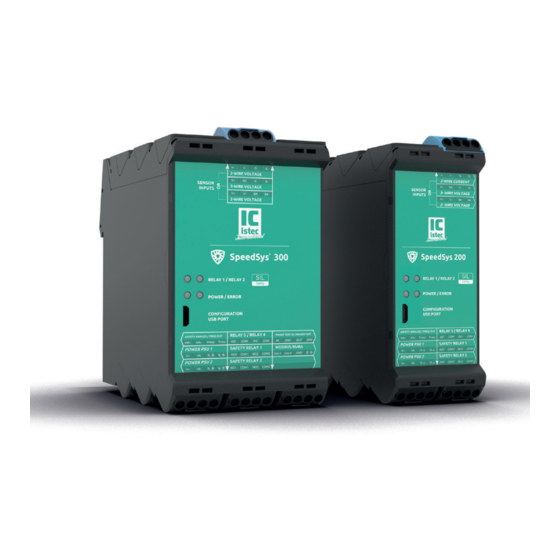
1.7 Parts and accessories SpeedSys 200 SpeedSys 200 module ƒ 9 removable connectors ƒ USB cable [USB A to USB B mini] ƒ SpeedSys 300 SpeedSys 300 module ƒ 11 removable connectors ƒ USB cable [USB A to USB B mini] ƒ... -
Page 13: System Overview
2. System overview 2.1 System description SpeedSys ODS is a compact, yet versatile overspeed protection system. It forms the last line of defence as an isolated layer of protection against dangerous overspeed situations for heavy and/or (semi-)critical machinery with high speed, mass and/or accumulated energy. -
Page 14: Application
2.3 Application SpeedSys ODS is a one-channel transmitter and is designed to be compatible with the most commonly used rotational speed probes; Hall-effect, electromagnetic (VR/MPU) and 2-wire dynamic current eddy current (proximity). The input circuitry is galvanically isolated allowing for advanced sensor monitoring and negating the necessity for additional external isolators. -
Page 15: Mounting And Installation
3. Mounting and installation 3.1 Module details The front label contains basic information about the connectors, wiring connections and module status. On the top of the module there are three connectors for the signals coming from the respective sensor type. The bottom has four connectors for the output signals: relays, analog and frequency outputs. - Page 16 Table 1: The connector arrangement and details are described in the table below. Bottom Name Sign Function Function Sign Name Safety Analog output + Safety Analog output - air vent OUTPUT Frequency output: signal Freq+ Frequency output: GND Freq- Power supply 1 + Power supply 1 - air vent POWER 1...
- Page 17 The images below show the pin confi guration on the physical unit. The label is designed to be intuitive and lead the user to the right pins and connectors. By virtually sliding the tables in the direction of the white arrow they become imaginary overlays to fi nd the right screw terminal.
-
Page 18: Module Dimensions And Installation
(ESD) according to EN 61340-5-1 and EN 61340-5-2. Observe the minimum clearances to allow for sufficient cooling. If the SpeedSys 200 or 300 is connected to circuits entering explosive areas, the general installation regulations for explosion protection EN 60079-14 and the applicable safety directives must be observed. - Page 19 MANUAL SPEEDSYS ODS - REV. APRIL 2024...
- Page 20 The electrical connections are established via screw terminals. Use a matching screwdriver to loosen and tighten the screws before and after inserting the wire into the clamp. The screw terminals’ specifications are: Wire clamping range: 0.13 mm² to 3.31 mm² ƒ...
-
Page 21: Connection Diagram
3.3 Connection diagram The fi gure below shows the electrical interfaces for the product. The sensor inputs are short circuit proof. The ATEX/IECEx certifi ed sensor input circuits are protected against overload and overvoltage. Supplying high voltages to the input circuits can blow the overvoltage fuse leading to an inactive unit. -
Page 22: Power Supply
WARNING: The use of an electromagnetic sensor (2-wire voltage sensor) requires a bridge to be set between the clamp contacts B03 and B04 (see connection diagram). In case the 2-wire voltage sensor is not used, the bridge must be removed, to ensure full functionality of the device. 3.4 Power supply SpeedSys ODS is certifi ed as a Separated Extra Low Voltage (SELV) system and requires a power supply that complies with this specifi cation. -
Page 23: Functional Grounding
internal galvanic isolators. Because of the integrated design of the isolators, SpeedSys ODS can keep ‘sight’ of sensors and feature advanced sensor monitoring like open circuit, close circuit, and voltage and/or current range monitoring. Additional barriers or isolators are therefore not required and in some cases would make it impossible to properly monitor the sensor health. - Page 24 intrinsically safe earth at the device side. If disturbances occur and inductive interferences need to be reduced, both ends of the shield might be connected to intrinsically safe earth (observe the general installation regulations for explosion protection EN 60079-14, if installed in explosive areas). In case of the 2-wire voltage sensor (electromagnetic sensor), SpeedSys ODS requires an installation in a controlled electromagnetic environment and the grounding of the sensor cable shield must be connected at the device side.
- Page 25 SpeedSys was designed and certified with the following cable and shielding configuration: Shield Shield Max. cable Sensor connection Description Type of cable Shielding instrument sensor length side side B01-B04 Eddy Current 1000 m Twisted pair (Li2YCY PiMF 2x B05-B08 Hall Sensor Typically, 300 m ≥...
- Page 26 See PSU and Shielding connection section for the connection cable shielding to ground (IE, IS). PSU and shielding connection diagram *) A zoned area can be regarded as an ESD controlled area and the shield can be single ended connected. In case the installation is in an ESD uncontrolled area the magnetic pick-up sensor cable must be connected to IE on both ends.
-
Page 27: Creating Voting Structures
3.7 Creating voting structures To obtain extra safety and/or availability for rotating machinery it is possible to create several hardwired voting structures with SpeedSys ODS. Hardwiring the voting structures avoids the introduction of interposing relays or tailing PLCs, which would inevitably add failure modes to the whole chain, negatively affecting the calculations for the SIL level and therefore the overall reliability. - Page 28 1oo2 To obtain extra safety, two relays can be connected 1oo2 in series to form a 1oo2 voting structure where the loop is interrupted, and the signal drops from high to low, if one of the two relays switches. A graphical representation for a connection with two terminals of safety relay 1 is shown below.
- Page 29 2oo2 To obtain extra availability, two relays can be 2oo2 connected in parallel to form a 2oo2 voting structure where the loop is interrupted, and the signal drops from high to low, if both relays switch. A graphical representation for a connection with two pins of safety relay 1 is shown below.
- Page 30 2oo3 To obtain extra safety and extra availability, three relays 2oo3 can be connected to form a 2oo3 voting structure where the loop is interrupted, and the signal drops from high to low, if any combination of two relays switch. The DPST relays allow for a hardwired voting structure as shown in the figure below where a signal (high to low) is given when two out of three relays switch.
-
Page 31: Binary Input/Proof Test In (Speedsys 300 Only)
2oo3 using safety relays 2 Module 1 Module 2 Module 3 To customer Wire out Wire out 3.8 Binary input/Proof test IN (SpeedSys 300 only) The binary input or, as it is shown on the label, the “PROOF TEST IN” is an open collector input exclusive for the SpeedSys 300. -
Page 32: Modbus Rtu (Speedsys 300 Only)
120 Ω resistor on the Modbus terminal is activated. More information, including an extensive register list, is available in the dedicated SpeedSys 300’s Modbus manual downloadable on Istec’s website. 3.10 Safety Instructions: Functional Safety SpeedSys ODS is equipped with two microcontrollers that mutually monitor each other, the ‘Duotec’... -
Page 33: Safety Instructions: Explosion Protection
3.11 Safety Instructions: Explosion protection SpeedSys ODS has the following explosion protection marking referring only to its sensor input circuitry: Ex II (1) G [Ex ia Ga] IIC Ex II (1) D [Ex ia Da] IIIC Category (1) G equipment: As a certified category (1) G equipment, the device may only be mounted in the ex- safe (non-hazardous) area. - Page 34 HAZARD: As an associated apparatus, the SpeedSys ODS must be mounted outside the explosive area. HAZARD: If the SpeedSys ODS is connected to circuits entering explosive areas, the general installation regulations for explosion protection EN 60079-14, the applicable safety directives, and the instructions of the operation manual must be observed.
-
Page 35: Programming
This programming manual is applicable to the software version 1.0. Note that Speedsys 200 and 300 have different software applications that look very similar, but will reject the other product. For this manual all screen captures are of the SpeedSys 300 software as it also includes all configuration settings for the SpeedSys 200. - Page 36 Note: Some anti-virus suites may block the software or require additional approvals to run third party applications. Information circles and field types The fields and buttons in the application come with a help text that can be seen by holding the mouse pointer over the information circles at the end of each field or over the button.
-
Page 37: Module Configuration
PC interface displays the port number, Access level shows the access permissions. Also, the Device status, the serial number and the tag number are displayed. By clicking Read device settings, the current settings are downloaded from the device into the PC software. 4.2 Module configuration After the software has connected to the device, the software is ready to read the configuration. - Page 38 ‘Active’. For more information on the Modbus connection consult the Modbus manual, which is downloadable from the Istec website. Secondly, the layer admin features higher permissions and can confi gure the voting structure, trip chain and dedicated administrator tags as well as device comments.
-
Page 39: Loading And Saving Configuration Files
4.3 Loading and saving configuration files A configuration file can be saved to a PC. A stored configuration file can be loaded into the software. The entry fields under ‘Configuration - admin’ are required to create an IEC 61511 compliant report. Make sure to enter correct data. These parameters are [TEXT] only and do not affect the operation of the unit. - Page 40 This page intentionally left blank MANUAL SPEEDSYS ODS - REV. APRIL 2024...
-
Page 41: Commissioning
5. Commissioning 5.1 Measurement parameters and settings To create a fully functioning configuration, all of the necessary fields and boxes need to be filled and selected. Measurement Measurement direction [TEXT] ƒ Three measurement directions can be selected: Axial the sensor measures along the machine’s axis. ƒ... - Page 42 M = module [mm/tooth] D = diameter [mm] n = number of teeth [teeth] (e.g. a diameter of 200 mm and 100 teeth result in a module of 2 mm/tooth). No. of pulses per revolution [INPUT] ƒ The number of pulses that corresponds to one revolution of the rotary setup. Required for correct rotational speed calculation and thus also reaction time under advanced settings.
- Page 43 Note: for the MPU/VR sensor there is 2,5 V offset on the signal to detect cable break. Sensor cut-in frequency [INPUT] ƒ The lower frequency limit of a reliable sensor signal. Below this limit the evaluated speed and acceleration are assumed and outputted as 0 and no bad pulse evaluation is performed.
- Page 44 parameter can be set between 1 and 5000. The acceleration is calculated by dividing a frequency diff erence by the time that has passed. The diff erence is calculated from averaged frequencies (see following fi gure). The time between the two frequency averaging periods is defi ned by the depth-parameter (as it is given as a number of pulses, the actual time is frequency dependent).
-
Page 45: Output Configuration
5.2 Output configuration The output tab enables the user to define the behaviour of the relays and the binary output (SpeedSys 300 only) as well as the analogue output. Each relay can be configured individually. Note that relay 1 and 2 are safety relays. Their output mode cannot be inverted;... - Page 46 Digital outputs Latching [INPUT] ƒ Enabling this setting will hold a relay in the NOT OK state after the activation of an alarm. It will remain in the activated state even when the alarm condition has been removed or resolved. The relay will return to its normal state after a reset. To reset the relay, use the “Test and Reset”...
- Page 47 Acceleration [INPUT] ƒ This category parametrizes the acceleration alarm condition. Enable the checkbox to activate acceleration alarm for the respective output. The upper limit for the rotational acceleration, as well as the hysteresis and delay can be individually confi gured. Overspeed / Underspeed / Acceleration Hysteresis and Delay [INPUT] ƒ...
- Page 48 Analog output range [INPUT] ƒ When the speed of the machine goes outside the value range set for the calibration the full range of the current output can be limited with this setting. Error output current [INPUT] ƒ Defines the output current when a diagnostic error occurs. Speed value for 20 mA [RPM] Speed value for 4 mA [RPM] Analog output range [mA]...
-
Page 49: Diagnostics
Determines the time frame in which 2 or more bad pulses will result in an error. SpeedSys 200 & 300 exhibits a double, identical pulse detection circuitry, to allow for self-diagnosis. Any relevant difference between the two pulses will lead to a... - Page 50 ‘bad pulse’ for the duration of the bad pulse window (see figure). This typically happens around the trigger level as one circuit evaluates it as ‘no pulse’ and the other lets the pulse through. Latch bad pulse error [INPUT] ƒ This will keep the unit in ‘safe state’...
-
Page 51: Process Data
5.4 Process data The Process Data tab displays relevant information about the current state of the process parameters as well as the status of the outputs. Furthermore, the minimum and maximum measurement values are stored for speed and acceleration. The two bottom rows of the Process data block show the ‘Analog output’... -
Page 52: Device Status
5.5 Device Status The Device Status window displays real-time information on different parameters. The user can observe the different supply voltages, the temperature and the sensor currents for each of the ‘Duotec’ channels. The minimum and maximum values of the latest sampling period are stored. -
Page 53: Report
5.6 Report By clicking on Generate PDF report, the Report window allows the user to obtain a PDF fi le that contains information on the confi guration of the SpeedSys ODS. The content can be individually selected. MANUAL SPEEDSYS ODS - REV. APRIL 2024... -
Page 54: Event Log
5.7 Event log The EVENT LOG tab allows the user to review and download all events. With a SpeedSys unit connected click the ‘Load event log’ button to download the event log from the SpeedSys unit. SpeedSys ODS does not contain an internal clock, it counts the time when it is powered up. - Page 55 Diagnostic error Description Non-safety parameter error Bad CRC of parameter group ‘configuration - user’ (DEVICE tab) or bad CRC of non-volatile status. Safety parameter error Bad CRC in one or more of the following parameter groups: DEVICE tab: configuration - admin ƒ...
- Page 56 Diagnostic error Description Watchdog reset detected Master MCU was reset by watchdog. Bad pulse detected The measured pulses are led through two comparison channels. At least two non- synchronism through the comparison channels were detected, see section 5.3 Diagnostics. Slave communication error Communication between master and slave MCU failed.
-
Page 57: Programming Parameters
Diagnostic error Description Slave UART watchdog error The slave MCU has stopped communication, which causes the device to enter the safe state. Slave runtime watchdog error Slave MCU was reset by watchdog during normal operation Slave start-up watchdog error Slave MCU was reset by watchdog during initial self-check (ROM, RAM, CPU) 5.8 Programming parameters After configuring all parameters, the configuration has to be written to the device. -
Page 58: Status Leds
In the safe state relays selected after ‘Diagnostics (safe state) on the OUTPUT tab will switch. 5.10 Status LEDs The front panel of the SpeedSys 200 & 300 has four LEDs for status indication. See the table below for a detailed description of their status. Status... -
Page 59: Service
Repairs may only be carried out by the manufacturer. 6.1 Spare parts - non listed- 6.2 Contact information Istec International Meer en Duin 8 2163 HA, Lisse, Netherlands +31 (0)252 433 400 www.istec.com... -
Page 60: Technical Information
7. Technical information 7.1 Labels and certifi cations Power supply (DC): 18..36 V , 315 mA Instrument earth connection (functional earth, not safety earth) The manufacturer declares that the product conforms to the applicable ATEX production directive 2014/34.EU. The manufacturer declares that the product conforms to the applicable standards. -
Page 61: Electrical Rating
Product identifiers H7368 Model SSYx00-000-00n (x = 2 or 3, n = model version) SSYx00-nnnnn (x = 2 or 3, nnnnn = numerical identifier) ISTSSYx00n (x = 2 or 3, n = numerical identifier) 7.2 Electrical rating Electrical rating for Ex-Circuits 2-wire current input Connectors B09, B10 Maximum output voltage (U... - Page 62 Electrical rating for non-Ex-Circuits Supply input Connectors A17, A18 and A21, A22 Voltage 18 V to 36 V Current consumption <315 mA Maximum voltage (U 250 V Current loop output Connectors A13, A14 Voltage 20 V Current rating 63 mA Maximum voltage (U 125 V Connectors B17, B18 / B19, B20 and...
- Page 63 “Game changing innovation for SIL rated overspeed protection“ Istec International Meer en Duin 8 2163 HA, Netherlands www.istec.com...
Need help?
Do you have a question about the SpeedSys 300 and is the answer not in the manual?
Questions and answers