Table of Contents
Advertisement
Quick Links
Please refer to the original service manual for:
Speaker system SB-CT500EG-K, Order No. PSG1511002CE (For SU-C500EB/EG/GN/PP only)
TABLE OF CONTENTS
1 Safety Precautions----------------------------------------------- 3
1.1. General Guidelines---------------------------------------- 3
1.2. Before Repair and Adjustment ------------------------- 4
1.3. Protection Circuitry ---------------------------------------- 4
1.4. Caution For AC Cord (For EB) ------------------------- 5
Model No.
Product Color: (S)...Silver Type
PAGE
1.5. Safety Parts Information----------------------------------6
2 Warning --------------------------------------------------------------7
2.1. Prevention of Electrostatic Discharge (ESD)
to Electrostatically Sensitive (ES) Devices ----------7
2.2. Precaution of Laser Diode -------------------------------7
© Panasonic Corporation 2015. All rights reserved.
Unauthorized copying and distribution is a violation
of law.
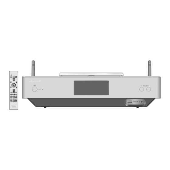
CD Stereo System
SU-C500EB
SU-C500EG
SU-C500GN
SU-C500PP
SU-C550EB
SU-C550EG
SC-C500EB
SC-C500EG
SC-C500GN
SC-C500PP
PSG1511001CE
A6
PAGE
Advertisement
Table of Contents

Related Manuals for Technics SU-C550EG


Summarization of Contents
Safety Precautions
1.1 General Guidelines
Provides general guidelines for safe handling and maintenance of the equipment.
1.2 Before Repair and Adjustment
Instructions on pre-repair checks and precautions before servicing the unit.
1.4 Caution For AC Cord
Safety warnings and precautions specific to the AC power cord usage and replacement.
Warnings and Precautions
2.1 ESD Prevention
Guidelines to prevent damage from static electricity to sensitive components during servicing.
2.2 Laser Diode Precautions
Safety precautions when working with the unit's laser diode, including radiation exposure.
Service Navigation and Mode
3.1 Service Information
Information on how to understand and service the model, including parts ordering.
6.1 Service Mode Tables
Tables detailing how to enter, operate, and interpret service mode functions.
Specifications
General Specifications
Details on power supply, dimensions, mass, operating temperature, and humidity.
Amplifier Specifications
Details on output power and load impedance for amplifier sections (SU-C500/SU-C550).
Bluetooth & Wi-Fi Specifications
Details on Bluetooth system specifications and Wi-Fi standards and frequency bands.
Controls and Operation
5.1 Remote Control Operation
Describes the function of each button on the remote control for unit operation.
5.2 Main Unit Operation
Identifies and explains the controls and indicators on the main unit.
Troubleshooting Guide
7.1 Preparations
Initial steps and checks, including power cord and capacitor discharge, before troubleshooting.
7.2 No Power Issues
Troubleshooting flow for the unit not powering on, checking SMPS and voltages.
7.4 No Display Issues
Troubleshooting steps for when the display does not show anything, checking connections and voltages.
7.6 Remote Control Issues
Troubleshooting steps when the remote control is unresponsive, checking IR and OLED signals.
7.15 No Speaker Sound
Troubleshooting steps for no audio output from speakers, checking AMP PCB and relays.
7.16 No Headphone Sound
Troubleshooting steps for no audio output from headphones, checking connections and headphone PCB.
Disassembly and Assembly
8.1 Screw Types
Lists the different types of screws used in the unit with their part numbers.
8.2 Disassembly Flow Chart
A visual flowchart outlining the sequence of disassembly for various unit components.
8.3 Component Locations
Diagrams showing the locations of major components and Printed Circuit Boards (PCBs).
8.4 Panel and Chassis Disassembly
Step-by-step instructions for removing external panels and chassis parts of the unit.
8.5 PCB Disassembly
Instructions for the careful disassembly of various Printed Circuit Boards (PCBs) within the unit.
8.7 Module and Antenna Replacement
Instructions for replacing Wi-Fi modules and antennas, including cable detachment.
Service Position
9.1 PCB Checking and Repair
Procedures for checking and repairing various PCBs and modules, including FFC connections.
Diagrams and Parts Lists
10 Block Diagram
A block diagram illustrating the system architecture and signal flow.
11 Wiring Connection Diagram
A diagram showing electrical connections between components and PCBs.
12.1 Cabinet Parts Location (SU-C500)
Exploded view showing cabinet parts location for SU-C500EB/EG/GN/PP models.
12.7 Mechanical Parts List
Comprehensive list of mechanical replacement parts with part numbers and quantities.
12.8 Electrical Parts List
Comprehensive list of electrical replacement parts with part numbers and quantities.
Need help?
Do you have a question about the SU-C550EG and is the answer not in the manual?
Questions and answers