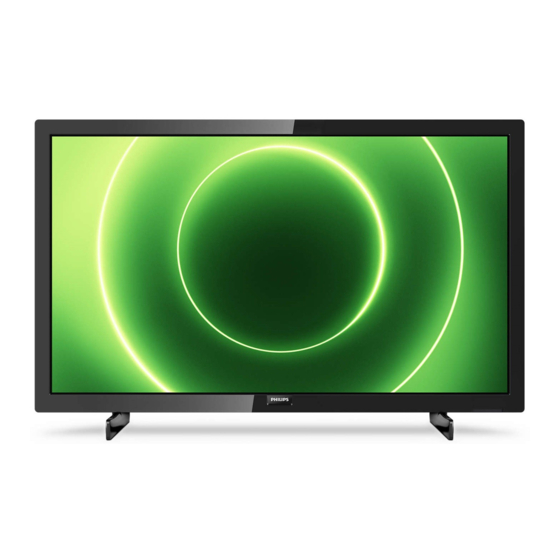
Table of Contents
Advertisement
Chassis name
TPM20.7E LA
Published by Doris /SC 2036 Quality
2020
TP Vision Netherlands B.V.
©
All rights reserved. Specifications are subject to change without notice. Trademarks are the
property of Koninklijke Philips Electronics N.V. or their respective owners.
TP Vision Netherlands B.V. reserves the right to change products at any time without being obliged to adjust
earlier supplies accordingly.
PHILIPS and the PHILIPS' Shield Emblem are used under license from Koninklijke Philips Electronics N.V.
Platform
MTK9288
Subject to modification
Model name
24PFS6805/12
24PFS6855/12
32PFS6805/12
32PFS6805/62
32PFS6855/12
32PHS6825/60
TPM20.7E
LA
32PHS6605/12
43PFS6805/12
43PFS6805/62
43PFS6855/12
32PFS6905/12
43PFS6825/60
3122 785 21051
2020-Sep-01
Advertisement
Table of Contents

Summarization of Contents
Product Information
Display Specifications
Details screen sizes, resolutions, supported input formats and timing.
Reception and Sound Features
Covers reception capabilities, tuner bands, sound enhancements, and output power.
Multimedia and Connectivity
Lists multimedia connections, supported file systems, and I/O ports.
Power Specifications
Details mains power requirements and operating ambient temperature.
Service Precautions and Notes
Safety Instructions and Warnings
Safety regulations, warnings for ESD, high voltage, and tool use during repair.
Repair Procedures and Technical Notes
Guidance on BLR/CLR, lead-free soldering, BOM identification, and schematic interpretation.
Abbreviation Glossary
Comprehensive list of technical abbreviations used in the manual.
Mechanical Instructions
Cable Dressing Procedures
Illustrates cable routing and connections for different chassis series.
Disassembly and Component Removal
Step-by-step guide for removing IR board, stand, rear cover, keyboard, SSB, PSU, speakers, WiFi, and LCD panel.
Service Modes
Service Alignment Mode (SAM)
Details SAM purpose, specs, activation, storage, and exit procedures.
Factory and Customer Service Modes
Covers Factory Mode activation/purpose and CSM activation, purpose, and exit.
Software and Error Management
Software Upgrading Procedures
Step-by-step guide for updating TV firmware via USB.
Error Code Handling and Clearing
Details on reading, understanding, and clearing error codes.
Setting Option Codes
Guide to setting specific option codes for panel types.
Troubleshooting Guides
Picture and Audio Diagnostics
Flowcharts for diagnosing picture and audio/sound related problems.
System and Intermittent Issue Diagnosis
Flowcharts for system-related issues and identifying intermittent problems.
Electrical Diagrams
Block Diagrams and Power Supply Overview
High-level block diagram and power architecture overview.
Detailed Circuit Diagrams
Schematics for SSB, interfaces (HDMI, USB, LVDS), memory, power, and control circuits.
IC Data Sheets
TAS5806MDDCPR (Audio IC)
Block diagram and pin details for the audio IC (U601).
Circuit Diagrams
SSB Power Supply Circuits
Diagrams for system power supplies across different SSB models.
Interface and Signal Circuitry
Diagrams for EMMC, UART, Audio, Video, HDMI, Tuner, USB, WIFI, CI, and LVDS interfaces.
Control and Memory Circuits
Diagrams for DRAM, IR/Keypad, and VCCK/DVSS.
Specific Board Schematics
Schematics for IR boards, LED panels, keyboard, and Ambilight panels.
Styling Sheets
Exploded Views and Parts Lists
Visual breakdowns and part identification for various series (24" 6805, 32"/43" 6805/6855, 32" 6825, 32" 6905, 43" 6825).
Dismantling and WEEE Compliance
Hazardous Materials and Disposal Requirements
Lists hazardous substances in LCDs and outlines EU WEEE disposal requirements.
Dismantling Procedures and Visual Guides
Step-by-step guides with images for removing batteries, circuit boards, and panel components.


Need help?
Do you have a question about the 24PFS6855/12 and is the answer not in the manual?
Questions and answers