Table of Contents
Advertisement
Quick Links
SERVICE
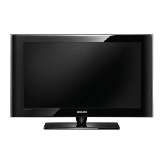
TFT-LCD TV
LE32A55*P /LE37A55*P/ LE40A55*P/ LE46A55*P/ LE52A55*P
Refer to the service manual in the GSPN (see the rear cover) for the more information.
LCD-TV
Chassis
: GPR32SEN
GPR37SEN
GPR40SEN
GPR46SEN
GPR52SEN
Model
: LE32A55*P
LE37A55*P
LE40A55*P
LE46A55*P
LE52A55*P
Manual
1. Precautions
2. Product specifi cations
3. Disassembly and Reassembly
4. Troubleshooting
5. Exploded View & Part List
6. Wiring Diagram
Contents
Advertisement
Table of Contents

Summarization of Contents
Precautions
Safety Precautions
Outlines essential safety measures to prevent damage and hazards like electrical shock.
Servicing Precautions
Details precautions to take before and during servicing of the LCD TV, including capacitor handling.
Electrostatically Sensitive Devices (ESD) Precautions
Provides techniques to reduce component damage from static electricity during handling.
Installation Precautions
Lists safety guidelines for safely carrying and installing the product, including ventilation.
Product Specifications
Feature & Specifications
Describes the key features and technical specifications of the LCD TV models.
Movie Plus: MJC (Motion Judder Cancellation)
Explains the Movie Plus technology for motion judder cancellation in HD film images.
Spec Comparison to the Old Models
Compares the specifications of the current model with older models for reference.
Accessories
Lists the included accessories for the product with their respective codes.
Disassembly and Reassembly
Disassembly
Details the step-by-step procedures for disassembling the LCD TV, including screw removal.
Troubleshooting
Troubleshooting (General)
Provides general troubleshooting steps for common issues like cable connections and power.
Alignments and Adjustments
Guides on performing general alignment and adjustments for the LCD TV.
Factory Mode Adjustments
Explains how to enter and use the factory mode for adjustments and panel checks.
White Balance - Calibration
Details the process for white balance calibration using specific patterns and equipment.
White Ratio (Balance) Adjustment
Describes how to adjust the white ratio in factory mode for different input sources.
Servicing Information
Provides information related to servicing, including firmware upgrades via USB.
EDID Self-Write Method
Explains the procedure for EDID self-write, especially related to HDMI version compatibility.
Exploded View & Part List
LE32A55*P Exploded View
Shows an exploded view of the LE32A55*P model, illustrating component placement.
LE37A55*P Exploded View
Provides an exploded view of the LE37A55*P model with component breakdown.
LE40A55*P Exploded View
Displays an exploded view of the LE40A55*P model, identifying parts.
LE46A55*P Exploded View
Presents an exploded view of the LE46A55*P model, detailing its components.
LE52A55*P Exploded View
Illustrates an exploded view of the LE52A55*P model, showing part relationships.
LE32A55*P Parts List
Lists the part numbers and descriptions for the LE32A55*P model.
LE37A55*P Parts List
Provides a detailed parts list for the LE37A55*P model with associated codes.
LE40A55*P Parts List
Offers a comprehensive parts list for the LE40A55*P model, including codes.
LE46A55*P Parts List
Contains the parts list for the LE46A55*P model, with part numbers and specifications.
LE52A55*P Parts List
Lists all parts for the LE52A55*P model, including their location and code numbers.
Wiring Diagram
Wiring Diagram
Shows the overall wiring diagram for the main boards and connections.
Wiring Picture
Provides a visual guide with pictures of the internal wiring and component locations.
Connector Functions
Explains the functions of key connectors and common symptoms for their failure.
Cables
Illustrates different cables used in the product with their part codes and specifications.
Schematic Diagram
MT8226 & EMMA Block Diagram
Presents a block diagram illustrating the MT8226 and EMMA IC functionalities.
MAIN POWER BLOCK
Details the schematic for the main power supply block of the TV.
SOUND
Shows the schematic diagram for the audio processing and output circuits.
Jack_In_Out-1 & Function
Illustrates the schematic for the first set of input/output jacks and their functions.
Jack_In_Out-2 & HDMI_Switch
Displays the schematic for the second set of input/output jacks and HDMI switching.
Jack_In_Out-3 & Tuner
Provides the schematic for the third set of input/output jacks and the tuner section.
Scaler-1 & Flash memory & Sub-Micom
Details the schematic for the Scaler-1 IC, flash memory, and sub-micom.
Scaler-2 & Main-DDR
Shows the schematic for the Scaler-2 IC and Main-DDR connections.
Scaler-Power & Service
Presents the schematic for the Scaler power supply and service functions.
FBE3 & LVDS Out
Illustrates the schematic for the FBE3 IC and LVDS output signals.
Emma2 & DTV-DDR
Displays the schematic for Emma2 and DTV-DDR components.
Emma2SL & PCMCIA & Flash memory
Shows the schematic for Emma2SL, PCMCIA, and flash memory.


Need help?
Do you have a question about the LE37A558P LE 40A552 and is the answer not in the manual?
Questions and answers