Advertisement
Quick Links
Advertisement

Related Manuals for Alcons LR15


Summary of Contents for Alcons LR15
-
Page 2: Table Of Contents
Table of contents _______________________________________________ Introduction ______________________________________________________________________________________ 3 Important safety instructions and precautions _________________________________________________________ 4 Installation_______________________________________________________________________________________ 5 Rigging components ______________________________________________________________________________ 6 Array configurations _____________________________________________________________________________ 11 Service and support ______________________________________________________________________________ 24 CE declaration of conformity _______________________________________________________________________ 26 Rigging manual LR15 Rev. 1.1... -
Page 3: Introduction
The rigging system supports different kinds of array assembling and has a working load limit of 18x LR15 or 9x LR18B cabinets under 10:1 safety. Manual This manual is written in a compact and easy readable way. You can contact Alcons Audio for more in-depth information on different items or situations Rigging manual LR15 Rev. 1.1... -
Page 4: Important Safety Instructions And Precautions
Do not stack the loudspeaker array on unstable ground or surface. If the array is stacked on a structure, platform, or stage, always check that the latter can support the total weight of the array. As a general rule, Alcons Audio recommends the use of safety straps at all times. -
Page 5: Installation
Unpacking Carefully open the shipping carton and inspect all the parts. Every Alcons product is thoroughly tested and inspected before leaving the factory and should arrive in perfect condition. If you find any damage, notify the shipping company immediately. Only you, the consignee, may initiate a claim for shipping damage. Be sure to save all packing materials for the carrier’s inspection. -
Page 6: Rigging Components
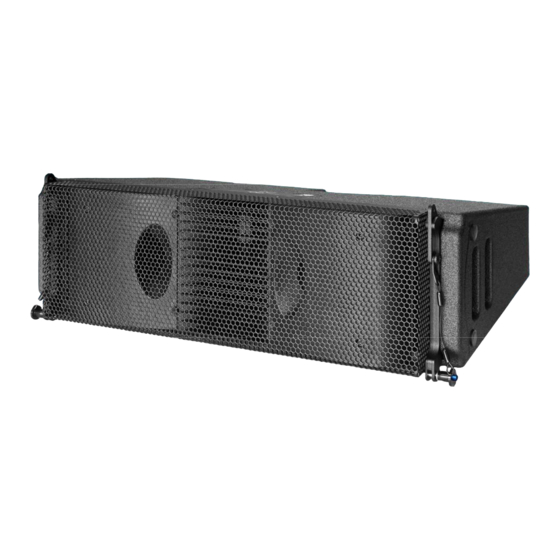
4. Rigging components __________________________________________ LR15 loudspeaker 1) LR15 cabinet LR15 cabinet (shown) 2) Front coupler front couplers, lockable with quick release pin 3) Recessed grip recessed area in the cabinet for handling 4) Pin angle setting pin determines the angle between the cabinets 5) Signal input/ link input/ link for the audio signal 6) Angle frame... - Page 7 4. Rigging components __________________________________________ LR15B loudspeaker 1) LR15B cabinet LR15B cabinet shown 2) Coupler Rotatable couplers, lockable with quick release pin 3) Bar handles Handles in the cabinet ensure easy handling 4) Bottom connector Connection with two holes, enabling a 2,5° splay angle Rigging manual LR15 Rev.
- Page 8 4. Rigging components __________________________________________ GRD15 The GRD15 enables the LR15 line-array modules to be flown and ground stacked. The grid can be suspended from multiple hoist positions on top of the grid or by means of a central “single pick-point” for smaller arrays; all points 14mm/0.55-in for 1,5T shackles. It has a mounting position and through hole for the Teqsas laser/ inclinometer.
- Page 9 4. Rigging components __________________________________________ GRD18EXTBR This is a “sliding” extension bar, which can be attached on top of the GRD15 or GRD15B, to extend the leverage capabilities of the GRD15(B), with larger centre-of-gravity (COG) array off-sets. With the GRD18EXTBR mounted at the front side of the GRD15(B), the upward array tilt is extended; With the GRD18EXTBR mounted at the rear side of the GRD15(B), the downward array tilt is extended.
- Page 10 4. Rigging components __________________________________________ CPLNGGRD15 The CPLNGGRD15 has a weight of 14 kg / 31 lb and is certified for a safety-rating of 10:1, for a front array of 9 (nine) cabinets LR15 and rear array for a rear array of 4 (four) cabinets LR15B on the hoist positions.
-
Page 11: Array Configurations
Array assembling can be done in two ways: Caterpillar style or Pre-rig style hoisting. This is determined by the available space, time or available parts. There are 12 user selectable logarithmic angles, which can be determined by the Alcons Ribbon Calculator™ simulation program. The angles are suitable for both caterpillar and pre-rig style array flying. - Page 12 5. Array configurations ___________________________________________ Cabinet connections LR15B LR15B has rotatable couplers, secured/ parked with a quick release pin. This pin is also used to make the connection to the GRD15B or the adjacent cabinet. It is also possible to use the LR15B as a single standing subwoofer. It then stands on its long or short side with slider feet.
- Page 13 5. Array configurations ___________________________________________ GRD15 options The GRD15 has multiple mounting options. The picture on the right shows the different pick-points for flying an array. The A1 & A2 marked points are the default hoist points. It is possible to use one pick point from the A1 linear pattern. Use it only for max.
- Page 14 5. Array configurations ___________________________________________ GRD15B options The GRD15B has multiple mounting options. The picture on the left shows the different pick-points for flying an array. The A1 & A2 marked points are the default hoist points. It is also possible to use one pick point from the A1 linear pattern.
- Page 15 The schematic picture below shows the possible array hang options a-d and stack arrangement e with LR15. The options also apply to GRD15B+LR15 As stated earlier, the array angles can be determined through the Alcons Ribbon Calculator™ simulation program. When ground stacking (e), ensure that the centre of gravity is well within the grid’s base area.
- Page 16 5. Array configurations ___________________________________________ GRD15B array options The schematic picture below shows the possible array hang options f-h and stack arrangement i & j with LR15B and LR15. Attaching LR15 to LR15B (flying or stacking) requires a second GRD15B (h). This is due to the fact that the LR15 has 3 pick points and LR15B a 4 pick points set-up.
- Page 17 5. Array configurations ___________________________________________ LR15 transport and array building options There are two transport/ array building options available for LR15 Caterpillar style: All LR15’s are connected horizontally/ face-down on 3 or 6-pack dollies. Angle-setting can only be done in the area of the array that is in full compress state, from where LR15’s are pulled up.
- Page 18 5. Array configurations ___________________________________________ LR15 transport and array building options Pre-rig style: All LR15(B) cabinets are connected vertically/ face-forward. This saves building space and enables pre-flight angle-setting. Tilting the already flown array on top of the pre-rigged array requires two motors, as the array needs to be dropped with the rear-side as low as possible, to be able to connect the rear latches.
- Page 19 (C). Take the first dolly away for storage. Pull the angle setting pins (4) out and make the correct angles using the angle arm. These angles are determined by the Alcons Ribbon Calculator™ simulation program. Continue doing this until all angles are set. Raise the entire array from the last wheel dolly (D).
- Page 20 5. Array configurations __________________________________________ Pre-rig style array assembling and hoisting With this method of array building the angle setting can be done at the warehouse or on-site. Also build space is kept to a minimum. It is preferable to use two motor hoists, when building large arrays. The numbers in the description below, correspond with the LR15 rigging components overview pictured earlier.
- Page 21 Take of the top-head from the FC3LR15. Attach the GRD15(B) to the top cabinet and secure the hoist(s) to the correct pick-point of the array (E). Ensure that the correct angles are set. As mentioned earlier, this is determined by the Alcons Ribbon Calculator™ simulation program.
- Page 22 5. Array configurations ___________________________________________ Using CNVB1518 Attach the CNVB1518 frame to the LR18 cabinet front couplers(A) and angle frame connection pin(B). Lower the LR18 array onto the top LR15 module on the Pre rig. You can also mount individual LR15 cabinets to the LR18 array. Mount the LR15 front couplers to the front inside points of the CNVB1518 and pin them. Make sure that the LR15 angle arm of the lower, second cabinet is turned into the angle frame for the angles 11.4°...
- Page 23 Make sure that the array is assembled on a flat and stable surface Begin by positioning GRD15/ GRD15B in ground stack mode. Ensure that the centre of gravity will be well within the GRD15(B) base. This can be determined by the Alcons Ribbon Calculator™ simulation program.
-
Page 24: Service And Support
Summary Alcons Audio BV warrants the original purchaser and any subsequent owner of each new Alcons product, for a period of six years limited from the date of the original purchase by the original purchaser that the new Alcons product is free of defects in materials and workmanship. Alcons Audio BV warrants the new Alcons product regardless of the reason for failure, except as excluded in this warranty. - Page 25 6. Service and support ___________________________________________ Contact information Mailing address: Alcons Audio BV De Corantijn 10 1689 AP ZWAAG The Netherlands Telephone: +31 (0)229 283090 World Wide Web: http://www.alconsaudio.com E-mail: info@alconsaudio.com Rigging manual LR15 Rev. 1.1...
-
Page 26: Ce Declaration Of Conformity
7. EC declaration of conformity ____________________________________ Alcons Audio BV De Corantijn 10 1689 AP ZWAAG The Netherlands States that the following products: LR15/ LR15B Rigging System are in conformity with the provisions of the following EC directives and applicable amendments:... - Page 27 Notes _________________________________________________________ Rigging manual LR15 Rev. 1.1...
Need help?
Do you have a question about the LR15 and is the answer not in the manual?
Questions and answers