Advertisement
Quick Links
Advertisement

Related Manuals for Alcons LR24/90


Summary of Contents for Alcons LR24/90
-
Page 2: Table Of Contents
Table of contents _______________________________________________ Introduction ______________________________________________________________________________________ 3 Important safety instructions and precautions _________________________________________________________ 4 Installation_______________________________________________________________________________________ 5 Rigging components ______________________________________________________________________________ 6 Array configurations _____________________________________________________________________________ 10 Service and support ______________________________________________________________________________ 21 CE declaration of conformity _______________________________________________________________________ 23 Rigging manual LR24 Rev. 1.21... -
Page 3: Introduction
1. Introduction __________________________________________________ Dear customer, Congratulations on your purchase of an Alcons Audio LR24 line array loudspeaker and thank you for your confidence in Alcons products. We are very honoured to welcome you to the growing family of Alcons ambassadors! For your safety, please read the Important safety instructions and the precautions section before rigging a loudspeaker array. -
Page 4: Important Safety Instructions And Precautions
Do not stack the loudspeaker array on unstable ground or surface. If the array is stacked on a structure, platform, or stage, always check that the latter can support the total weight of the array. As a general rule, Alcons Audio recommends the use of safety straps at all times. -
Page 5: Installation
Unpacking Carefully open the shipping carton and inspect all the parts. Every Alcons product is thoroughly tested and inspected before leaving the factory and should arrive in perfect condition. If you find any damage, notify the shipping company immediately. Only you, the consignee, may initiate a claim for shipping damage. Be sure to save all packing materials for the carrier’s inspection. -
Page 6: Rigging Components
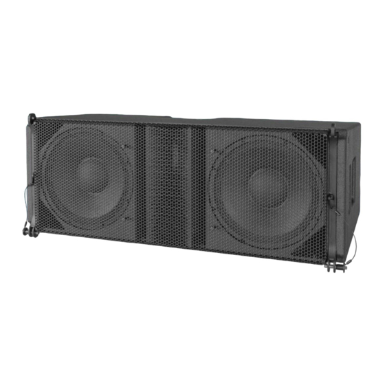
4. Rigging components __________________________________________ LR24 loudspeaker 1) LR24 cabinet LR24 cabinet (shown) 2) Front coupler Front couplers, lockable with quick release pin 3) Bar handles Handles in the cabinet ensure easy handling 4) Pin angle setting Pin determines the angle between the cabinets 5) Angle arm + lever Lever to turn the angle arm 6) Signal input/ link... - Page 7 4. Rigging components __________________________________________ GRD24B The GRD24B enables the LR24 line-array modules to be flown and ground stacked. The grid can be suspended from multiple hoist options on top of the grid or with the central “single pick-point” bar for smaller arrays (all points 14mm/0.55- in for 1,5T shackles).The GRD18B has a weight of 35 kg / 77 lb and is certified for 24 cabinets LR24 GRD28B...
- Page 8 4. Rigging components __________________________________________ PRRGL24 The LR24 is transported with 4 units on the PRRGL24 pre-rig dolly frame, facilitating curved or straight stacks. The dolly frame also enables a ground-stack configuration. With the optional detachable legs the tilt-angle can be adjusted.The LR24 is transported with 4 units on the PRRGL24 pre-rig dolly frame, facilitating curved or straight stacks.
- Page 9 There are 10 user selectable logarithmic angles, which can be determined by the Alcons Ribbon Calculator™ simulation program. The angles are suitable for both Fly and Compression mode array flying.
-
Page 10: Array Configurations
5. Array configurations ___________________________________________ GRD24B options The GRD24B has multiple mounting options. The picture on the left shows the different pick-points for flying an array. The A1 & A2 marked points are the default hoist points. It is also possible to use one pick point from the A1 linear pattern. - Page 11 The schematic picture below shows the possible array hang options a-d and stack arrangement e with LR24. As stated earlier, the array angles can be determined through the Alcons Ribbon Calculator™ simulation program. When ground stacking (e), ensure that the centre of gravity is well within the grid’s base area.
- Page 12 5. Array configurations ___________________________________________ LR24 transport and array building options Curved pack/ Fly mode: All LR24 cabinets are connected vertically in a curved pack. This saves building space and enables Pre-flight angle-setting. All red pins are stowed in their parking holes. The bottom cabinet is mounted to the PRRGL24 according to the picture on the right.
- Page 13 5. Array configurations ___________________________________________ LR24 transport options Straight pack/ compression mode: All LR24 cabinets are connected vertically in a straight pack. This saves building space and enables pre-flight angle-setting. All red pins are placed in the angle arm hole. Except the angle arm of the top cabinet.
- Page 14 (4) out and set the correct angles using the Fly slot in the angle arm (5). These angles are determined by the Alcons Ribbon Calculator™ simulation program. Hoist the first pack from the pre-rig (B). Connect the necessary cabling to the signal input/ link (6) connectors.
- Page 15 5. Array configurations ___________________________________________ Storage PRRGL24 dollies The dollies can be stored on top of each other, with or without the PRRGL24TOP plateaus. Turn the pre-rig angle arm to the middle locking pin position and pin it. The PRRGL24 can now be placed on top of each other.
- Page 16 5. Array configurations ___________________________________________ Compression mode array assembling and hoisting This description features an 8 piece array connected to GRD24B This flying option is best suited for small 4->12 pcs arrays. The cabinets are transported in a straight pack. The red buttoned pin (9) is crucial in this situation. It ensures that the cabinets (1) will stay in a 0°...
- Page 17 5. Array configurations ___________________________________________ Take the top cabinet angle arm out of the transport position and put the red pin (9) in. Choose the angles of al cabinets by aligning the angle pin (4) with the bottom compression fly slot in the angle arm (5). The angle setting can be done at the warehouse or on-site.
- Page 18 5. Array configurations ___________________________________________ Landing the array compression mode De-compress the cabinets to 0° by releasing the tension of the lever hoist. The whole array should now be hanging vertical. Remove the PBFRML24 and attach the PRRGL24 pre-rig. This is a two man job. The pre-rig angle arm is not locked with its pin, but is connected directly to the bottom cabinet connection. Put the red buttoned pins (12) into the angle arms of the first 4 piece array.
- Page 19 Make sure that the array is assembled on a flat and stable surface Begin by positioning PRRGL24 to the desired location. Ensure that the centre of gravity will be well within the mounting base. This can be determined by the Alcons Ribbon Calculator™ simulation program.
- Page 20 Begin by positioning the GRD24B at the desired location. Ensure that the centre of gravity will be well within the mounting base. This can be determined by the Alcons Ribbon Calculator™ simulation program. Start disassembling an LR24 pack on a PRRGL24 or use single LR24’s. Turn the cabinets 180° in the vertical plane and connect the first one to the GRD24B.
-
Page 21: Service And Support
Alcons product is free of defects in materials and workmanship. Alcons Audio BV warrants the new Alcons product regardless of the reason for failure, except as excluded in this warranty. In order to obtain warranty, you must keep the original sales receipt to establish the exact date of purchase. - Page 22 6. Service and support ___________________________________________ Contact information Mailing address: Alcons Audio BV De Corantijn 69 1689 AN ZWAAG The Netherlands Telephone: +31 (0)229 283090 World Wide Web: http://www.alconsaudio.com E-mail: info@alconsaudio.com Rigging manual LR24 Rev. 1.21...
-
Page 23: Ce Declaration Of Conformity
7. EC declaration of conformity ____________________________________ Alcons Audio BV De Corantijn 69 1689 AN ZWAAG The Netherlands States that the following products: LR24 Rigging System are in conformity with the provisions of the following EC directives and applicable amendments: Machinery 2006/42/EC... - Page 24 Notes _________________________________________________________ Rigging manual LR24 Rev. 1.21...
Need help?
Do you have a question about the LR24/90 and is the answer not in the manual?
Questions and answers