Table of Contents
Advertisement
Quick Links
SERVICE MANUAL
Differences Manual
MODEL
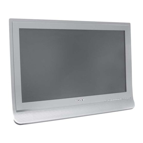
KDL-20B4050
KDL-23B4050
KDL-26B4050
Note: This Service Manual shows only the differences from KDL-20/23/26B4030.
Refer to the Service Manual (9-927-595-xx) of KDL-20/23/26B4030, also for repair.
COMMANDER
DEST
RM-ED009
AEP
RM-ED009
AEP
RM-ED009
AEP
KDL-20B4050 / KDL-23B4050 / KDL-26B4050
- 1 -
SE2
MODEL
KDL-20B4050
KDL-23B4050
KDL-26B4050
FLAT PANEL COLOR TV
SE2
RM-ED009
CHASSIS
COMMANDER
DEST
RM-ED009
UK
RM-ED009
UK
RM-ED009
UK
RM-ED009
Advertisement
Table of Contents

Summarization of Contents
Section 5 Exploded Views
5-1. Chassis (20 & 23 inches)
Exploded view of the chassis for 20 and 23-inch models.
5-2. Chassis (26 inches)
Exploded view of the chassis for 26-inch models.
5-3. Rear Cover, Power Supply Cords & Bezel (20 & 23 inches)
Exploded view of rear cover, cords, and bezel for 20/23-inch models.
5-4. Rear Cover, Power Supply Cords & Bezel (26 inches)
Exploded view of rear cover, cords, and bezel for 26-inch models.
Section 1 General
Lead Free Soldered Boards
Details about using lead-free solder and precautions.
Connectors
21 Pin Connector (SCART)
Pin configuration and signal levels for the SCART connector.
HDMI Connector
Pin assignments for the HDMI connector.
15 Pin D Sub Connector (PC)
Pin assignments for the D-Sub (PC) connector.
SE2 Self Diagnostic Software
LED Error Codes
Lists LED flash codes, their descriptions, checks, and actions.
Error Descriptions
Explains the meaning and related faults for identified errors.
Section 2 Disassembly
2-1. Rear Cover Removal (20 & 23 inches)
Steps for removing the rear cover for 20 and 23-inch models.
2-2. Rear Cover Removal (26 inches)
Steps for removing the rear cover for 26-inch models.
2-3. Loudspeaker Removal (20 & 23 inches)
Instructions for removing loudspeakers from 20 and 23-inch models.
2-4. Loudspeaker Removal (26 inches)
Instructions for removing loudspeakers from 26-inch models.
2-5. B1 Board Removal
Procedure for removing the B1 board.
2-6. GS1/GS2/GS5 Board Removal
Steps for removing GS1, GS2, and GS5 boards.
2-7. H Board Removal
Procedure for removing the H board.
2-8. LCD Panel Removal (20 inches)
Steps for removing the LCD panel from 20-inch models.
2-9. LCD Panel Removal (23 inches)
Steps for removing the LCD panel from 23-inch models.
2-10. LCD Panel Removal (26 inches)
Steps for removing the LCD panel from 26-inch models.
Section 3 Circuit Adjustments
3-1. Electrical Adjustments
Guide to entering service mode and performing electrical adjustments.
3-2. TT Mode
Description of TT mode functions and selection.
3-3. TT OSD Labels
Explanation of OSD labels used in TT mode.
Section 4 Diagrams
4-1. Block Diagram
Overall block diagram of the system.
4-2. Circuit Board Location
Identifies the physical location of main circuit boards.
4-3. Schematic Diagrams and Printed Wiring Boards
Reference for schematic diagrams and printed wiring boards.
Section 6 Electrical Parts List
B1 Board Complete Parts List
Parts list for the B1 board, common and model-specific.
H Board Complete Parts List
Parts list for the H board.
Accessories and Connectors
List of accessories and connectors.
Remote Commander
Details about the remote commander.


Need help?
Do you have a question about the KDL-23B4050 and is the answer not in the manual?
Questions and answers