Table of Contents
Advertisement
Advertisement
Table of Contents

Related Manuals for Jupiter J144


Summary of Contents for Jupiter J144
- Page 1 J100 Video Wall Controller Hardware Manual June 12, 2023 A-JSE-000-03, Rev. A...
- Page 2 Jupiter Systems owns the copyright for this manual. Use or reproduction of this manual in parts or entirety without the authorization of Jupiter Systems is prohibited. The contents of this manual are subject to change without notice to improve quality.
-
Page 3: Table Of Contents
Table of Contents 1. I HAPTER NTRODUCTION 1.1 J100 Compact Video Wall Controller ....................2 1.2 J400/600 Chassis Based Video Wall Controllers................3 1.3 Jupiter Systems Portfolio of Products....................4 2. C HAPTER OMPACT IDEO ROCESSORS 2.1 Ordering Information ........................6 2.2 Specifications...........................7 2.3 Indicators ............................9 3. - Page 4 J100 Hardware Manual Table of Contents IST OF IGURES IST OF ABLES NDEX J100 Hardware Manual...
-
Page 5: Chapter 1. Introduction
Jupiter Systems J-Series Video Wall Controllers (referred to as JVWC hereafter) are highly stable video wall processors which fully support 4K UHD inputs and outputs. Jupiter offers the J400 and J600 chassis based models as well as compact, fixed interface J100 models to provide affordable support for a variety of video wall applications. -
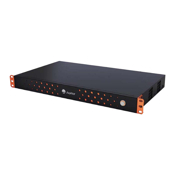
Page 6: J100 Compact Video Wall Controller
With the J100 Client or J400/J600 Client management software set up is a snap. Both chassis based and fixed interface models may be controlled via API. See the J-Series Video Wall Controller API Manual for more information. -
Page 7: J400/600 Chassis Based Video Wall Controllers
1.2 J400/600 Chassis Based Video Wall Controllers All J400/J600 and J100 models are 19" units designed to fit into standard 19" mounting racks. The J600 is 6RU (rack units), the J400 is 4RU, and the J100 models are 1RU. Each J-Series model supports a different amount of inputs and outputs. -
Page 8: Jupiter Systems Portfolio Of Products
Jupiter System provides a large portfolio of video processing systems and innovative displays. Capable of integrating any type of video and data source on any display wall configuration, Jupiter products and solutions are widely used in diverse applications such as Video Conference Rooms, Public Utility Control Centers,... - Page 9 & entertainment venues and digital signage. All J100 models have two variations, one with a preview option, one without. The preview option models are designated by "-PV," so the J188 models would be J188-PV and J188.
-
Page 10: Chapter 2. Compact Video Wall Processors
Chapter 2: Compact Video Wall Processors 2.1 Ordering Information Table 2.1: J100 Ordering Information Product Name JOQS Number Description J188 J-188 1RU, 19" fixed interface model with 8 FHD HDMI inputs and 8 FHD HDMI outputs J188-PV J-188-PV 1RU, 19" fixed interface model with 8 FHD HDMI inputs and 8 FHD HDMI outputs. -
Page 11: Specifications
Specifications 2.2 Specifications Table 2.2: J100 Specifications Feature Description Form Factor Maximum Power Consumption MTBF 100,000 hours Interfaces Input Channels – J188 models 8 FHD HDMI (HDMI IN 1-8) Input Channels – J148 models 4 FHD HDMI (HDMI IN 1-4) Input Channels –... - Page 12 Chapter 2: Compact Video Wall Processors Table 2.2: J100 Specifications (Continued) Feature Description Environmental 0° – 40°C (32° to 104°F) Operating Temperature -10° – 66°C (14° to 150°F) Storage/Transport 10 – 90% (Non-condensing) Operating Humidity 5 – 95% (Non-condensing) Storage/Transport Humidity...
-
Page 13: Indicators
Indicators 2.3 Indicators Figure 2.2: J188-PV Rear View Figure 2.3: J148-PV Rear View Figure 2.4: J144-PV Rear View Table 2.3: J100 Indicators Interface/Indicator Light Indicates Green on Connection made Green blinking Data transfer activity Green off No Activity RJ45, Ethernet... - Page 14 This page has been intentionally left blank J100 Hardware Manual...
-
Page 15: Chapter 3. Installation
Chapter 3 NSTALLATION The J100 models are designed to be installed on a standard 19 inch rack. However they also have feet and may be set horizontally on a table or shelf. Please follow all safety precautions, environmental considerations, and power and ground considerations 3.1 J100 Models Installation... - Page 16 Power on the J100 unit Connect to management The J100 may be managed locally through a serial connection or via the network through an Ethernet connection. Preview models have a separate Ethernet connection for supplying the preview stream to the JVWC software.
- Page 17 • Lights on unit (The power button on front will light up when unit has power) • Network connection lights are working properly • You can connect to the J100 through software (see J100 Client Manual) • Status lights are behaving properly •...
-
Page 18: Rack Mount Installation
J100 chassis in an environment compatible with the TMRA. Beware of reduced air flow Installation of the J100 chassis in a rack should be such that the amount of airflow required for safe operation of the J100 chassis is not compromised. -
Page 19: Required Tools
Ensure that proper cable grades are used for all system and network connections. For best results, use the cables and connectors recommended in this document. • Your J100 unit can become hot while operating. Always turn off your computer, unplug it, then wait for hot surfaces to cool before touching your J100 unit. •... -
Page 20: Install Location
J100 models have ventilation holes on either side. Air is pulled in from the right side and pushed out the left side. Do not block either side. For this reason J100 models cannot be mounted on the side or set on the side on a desk or shelf. -
Page 21: Chapter 4. Technical Support
4.2 Technical Assistance If you require technical assistance, please contact Jupiter Systems' technical support team. Please provide as much information to the support team about the fault and any steps you have taken in trying to resolve the issue. - Page 22 This page has been intentionally left blank J100 Hardware Manual...
- Page 23 Figure 3.2 Typical Mapping of J100 Outputs to Displays ....... .
- Page 24 This page has been intentionally left blank J100 Hardware Manual...
- Page 25 Table 2.1 J100 Ordering Information ........
- Page 26 This page has been intentionally left blank J100 Hardware Manual...
- Page 27 Reduced air flow J100 1, 3 Storage/Transport Humidity J-Series Architecture J144 J148 J188 Storage/Transport Temperature LightSpeed operating system J144 LightSpeed technology J148 J188 Maximum Altitude J144 Temperature J148 Ambient operating J188 Typical Mapping of J100 Outputs to Displays Mechanical loading...
- Page 28 J100 Hardware Manual Index Uneven mechanical loading Video Wall Controllers Unpack J100 Hardware Manual...
Need help?
Do you have a question about the J144 and is the answer not in the manual?
Questions and answers