Table of Contents
Advertisement
Quick Links
INSTALLATION AND
OPERATING MANUAL
Risk of Electric shock. If the information in this manual is not followed exactly, a fire or
electricution may result causing property damage, personal injury, or loss of life.
Do not store or use gasoline or other flammable vapors and liquids or other combustible
materials in the vicinity of this or any other appliance.
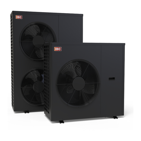
Hydronic Heat Pump
HPX 3 (3 ton model #IHEXXF1-003T)
HPX 5 (5 ton model #IHEXXF1-005T)
WARNING
Advertisement
Table of Contents
Troubleshooting

Related Manuals for IBC HPX 5

Summarization of Contents
2.0 Manual Safety Markings
Important Safety Instructions
Installation, start-up, and servicing must be performed by competent, qualified, licensed, and trained technicians.
Known Contaminants
Lists corrosive contaminants that can damage the heat exchanger and system components.
3.0 Specifications
3.1 Cabinet Dimensions
Provides dimensional drawings for HPX-Series units, showing front, side, and top views.
3.2 Connection Specifications
Details the NPT-M threaded fittings for water inlet/outlet and knock-outs for power/control.
3.3 Capacities and COPs
Presents tables of heating capacity and COP values across various operating conditions.
4.0 Introduction
4.1 Standard Features and Benefits
Highlights key features like high efficiency, EVI design, modulating operation, and quiet performance.
4.2 Warranty
Outlines the 2-year parts and 5-year compressor limited warranty for residential and commercial applications.
5.0 Before Installation
Precautions
Lists essential precautions for proper sizing, installation location, and protection from contaminants.
6.0 Installation
6.1 Code Requirements
Details compliance with national and local electrical and safety regulations for installation.
6.2 Determining Location of the Appliance
Guides on selecting an appropriate location, considering clearances and environmental factors.
6.3 Important Design Considerations
Discusses crucial factors like water temperature, COP impact, and building heat loss for optimal design.
6.4 Water Piping
Recommends unions for connections and details water quality requirements for system longevity.
6.5 Hydronic Heat Pump Circulator Selection
Provides guidance on selecting an appropriate circulator based on head loss and flow rate requirements.
Propylene Glycol Usage
Advises on the use of non-toxic propylene glycol for freeze protection and its system implications.
6.6 Relief Valve
Details requirements for installing and discharging the relief valve safely to prevent injury.
6.7 General Piping Best Practices
Covers primary/secondary piping, hydraulic separators, and buffer tank sizing recommendations.
6.8 Electrical Connections
6.8.1 Power Management, Quality and Electrical Protection
Emphasizes clean power supply, surge protection, and safe electrical practices for the heat pump.
6.8.2 240VAC Line-Voltage Hook-up
Details the process for connecting the unit to the grid power using separate fused circuits and contactors.
6.8.3 Hydronic Heat Pump Circulator
Explains the field installation and wiring of the heat pump circulator using a pump control module.
6.8.4 Thermostat Wiring
Guides on connecting thermostat control wiring to the J4 terminals for heating or cooling signals.
6.8.5 Control Wiring Overview
Combines thermostat and pump wiring diagrams, adding details for cooling and system pump control.
6.8.6 Other Wiring
Covers optional low voltage connections like auxiliary interlocks for external safety devices.
6.8.7 Buffer Tank Sensor Wiring
Details attaching the 10kΩ tank sensor for stand-alone operation near the field-wiring board.
7.0 About the Hydronic Heat Pump Controller
7.1 Use with the IBC Sky 35 Controller
Explains setup and configuration using the IBC Sky 35 controller via a 2-wire communication cable.
7.2 Use in Stand-alone Mode
Details using the HPX in stand-alone mode with a thermostat or sensor and touchscreen interface.
7.2.2 Adjusting Temperature Units
Guides on changing temperature units between Fahrenheit and Celsius via the Parameters menu.
7.2.3 Adjustment for Cooling Mode
Instructs on activating cooling mode by changing the 'Cooling Mode' parameter to 'Yes'.
8.0 Before Operating the Hydronic Heat Pump
Checklist for Electrical and Water Connections
A checklist covering electrical conditions, piping, and outside unit checks before powering on.
9.0 Heat Pump Operation
Starting and Shutting Down the Heat Pump
Provides a start-up checklist including electrical connections, system pressure, and glycol concentration.
10.0 Service and Maintenance
Maintenance Checklist for Homeowner
Outlines basic maintenance tasks for homeowners, such as inspecting for noises and keeping the unit clean.
Maintenance Checklist for Heating Contractor
Lists detailed maintenance tasks for qualified technicians, including calibration, cleaning, and testing.
11.0 Troubleshooting
Preliminary Checks
Basic checks including power, safety lockout, wiring, and water pressure confirmation.
Electronic Components Checks
Guidance on checking components like temperature sensors, flow sensors, and high limit switches.
Temperature Sensors Testing
Details testing temperature sensors by measuring resistance and comparing it to environmental values.
Troubleshooting Error Messages
Lists common error codes, their descriptions, and recommended fixes or comments for troubleshooting.
Temperature Issues Diagnosis
Identifies issues like low heat, temperature exceeding limits, and zones not heating properly.
Miscellaneous and Cycling Issues
Addresses 'ghost' calls, rapid cycling, and other operational problems with their fixes.
12.0 Exploded Views of the HPX Series Heat Pumps
HPX 3 Parts Diagram
Illustrates the components of the HPX 3 model with item numbers and descriptions.
HPX 5 Parts Diagram
Illustrates the components of the HPX 5 model with item numbers and descriptions.
13.0 Appendices
Wiring Diagrams
Provides detailed wiring diagrams for the HPX 3 and HPX 5 internal electrical connections.
Need help?
Do you have a question about the HPX 5 and is the answer not in the manual?
Questions and answers