Advertisement
Quick Links
Advertisement

Related Manuals for ALC 40003


Summary of Contents for ALC 40003
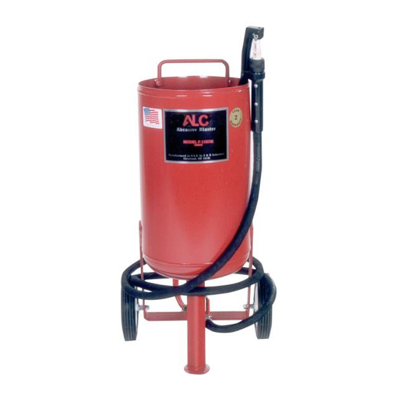
- Page 1 40001, 40003, 40004 and 40005 PRESSURE BLASTER with Deadman Control System OPERATION GUIDE DIVISION OF S&H INDUSTRIES 5200 Richmond Road Cleveland, OH 44146 Phone 216-831-0550 Toll Free 800-253-9726 Fax 216-831-9573 www.shindustries.com E-mail: www.service@shindustries.com Rev. 2/8/19...
- Page 2 Page 2 WARNING! Do not use an ALC Pressure Blaster until you have read this manual and you understand its contents and warnings. These warnings are included for the health and safety of the operator and those in the immediate vicinity. Keep this manual for future reference.
- Page 3 40001, 40003, 40004, 40005 Assembly Instructions Page 3 ASSEMBLY INSTRUCTIONS NOTE: Refer to diagrams on page 9 when assembling. Attach wheel assemblies to wheel support as shown in inset #1 (p. 13). Do not tighten nut snugly against wheel hub, as some movement is required to allow free rolling of wheels.
- Page 4 40001, 40003, 40004, 40005 Assembly Instructions Page 4 PRESSURE BLASTER SAFETY PROCEDURES – CAUTION: R EAD THESE SAFETY PROCEDURES IN THEIR ENTIRETY PARTS OF THE PERATING NSTRUCTIONS ARE WITHIN THESE ARNINGS These procedures are not intended to be exhaustive due to the many variables in the abrasive blasting field.
- Page 5 40001, 40003, 40004, 40005 Assembly Instructions Page 5 Drain air out of tank through the inlet valve and disconnect power before maintenance cleaning of any kind. When removing nozzle, caution must be exercised as air pressure may still be in the hose if the nozzle is plugged.
-
Page 6: Operating Technique
40001, 40003, 40004, 40005 Assembly Instructions Page 6 OPERATING INSTRUCTIONS OPERATING TECHNIQUE: Connect air hose to air inlet valve. Manufacturer recommends using minimum incoming air hose of 1/2” I.D. Using an air hose smaller than 1/2” I.D. will restrict air volume and result in poor unit operation. - Page 7 40001, 40003, 40004, 40005 Assembly Instructions Page 7 NOZZLE SELECTION CHART PART NO. NOZZLE I.D. BLASTING AREA ABRASIVE SQ. FT./MIN. USAGE/HR. 3/32” 40067 100 lbs. 40068 1/8” 1 to 1-1/2 150 lbs. 5/32” 40069 2 to 2-1/2 200 lbs. 3/16”...
- Page 8 40001, 40003, 40004, 40005 Assembly Instructions Page 8 AIR COMPRESSOR RECOMMENDATION: To permit efficient operation of your air compressor, follow these guidelines: Use a smaller size nozzle to control the demand of air. Do not blast continuously. Stop blasting operation periodically to allow the compressor to cool.
- Page 9 40001, 40003, 40004, 40005 Assembly Instructions Page 9 ABRASIVE AND PRESSURE GUIDE Material to Be Cleaned Air Pressure Abrasive Grit Size Steel vats 100-125 psi Coal Slag Garnet 30/50 20/40 Auto fenders 50-80 psi Coal Slag Garnet 80/120 20/40 Brick and block...
-
Page 10: Troubleshooting Tips
40001, 40003, 40004, 40005 Assembly Instructions Page 10 TROUBLESHOOTING TIPS PROBLEM/CAUSE POSSIBLE SOLUTION Surging of blast flow: Air pressure too low Check pressure gauge on compressor Too much media Adjust media valve 40200 Excessive media consumption: Media valve open too far... -
Page 11: Maintenance
Replace the nozzle when it wears to the next larger size (at this time the Venturi effect of the nozzle is inefficient). Check the urethane gasket in the pull-up closure when the air leaks excessively from the opening (make sure the gasket is free from media). Note: Replace with genuine ALC parts – do not substitute. - Page 12 5/8” diameter axle (F-300) 40168 Handle 10973 11500 Pivot tension spring 10974 Palnuts for S-40 axle 1/2” moisture separator (optional) 40207 40229 Pressure relief valve Moisture separator is standard on models 40004 and 40005. It is optional for models 40001 and 40003.
- Page 13 40001, 40003, 40004, 40005 Assembly Instructions Page 13...
-
Page 14: Limited Warranty
40001, 40003, 40004, 40005 Assembly Instructions Page 14 Disclaimer of Warranties. S & H Industries, Inc. ("Seller") makes no warranties with respect to any goods delivered to Buyer or users except as specifically set forth within this manual. S & H INDUSTRIES, INC.
Need help?
Do you have a question about the 40003 and is the answer not in the manual?
Questions and answers