Table of Contents
Advertisement
Quick Links
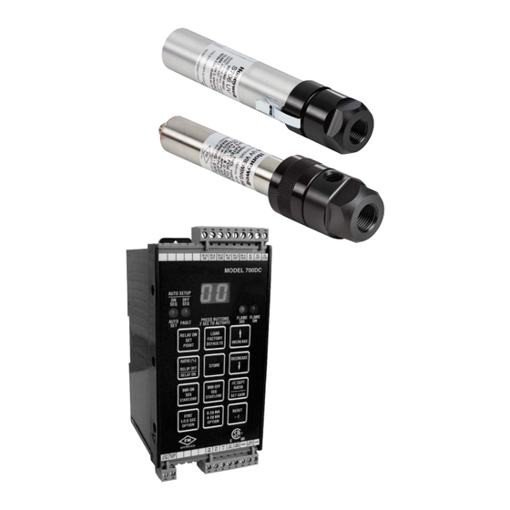
Honeywell Model 700/800 Signal
Processor and Viewing Head
APPLICATION
The Honeywell Model 700ACSP and Model 700DCSP
signal processors are single-channel, fail safe, flame
monitoring systems when used In conjunction with the
S70X/S80X viewing heads. They offer easy setup,
excellent discrimination, and high reliability.
FEATURES
Viewing heads are interchangeable between the two
signal processor models. Any viewing head in the two
families will work with any of the signal processors.
Two signal processor models are available:
• Model 700ACSP Universal 85-265 VAC powered, plus
24VDC backup.
• Model 700DCSP 22-26VDC powered, plus 24VDC
backup.
The two Model 700 signal processors are similar, with 12
push-buttons, a two-digit numeric display, and four LED
status indicators for operator interface. The only
difference between the two is that one accepts AC power
and the other accepts DC power. Both models also accept
24VDC backup power. Most of the signal processor
connections are made through Phoenix plug-in
connectors. Communication connections are made
through modular phone jacks located at the top of the
signal processors (Fig. 9).
Both signal processor models mount on a standard 35
mm DIN rail. They snap into place and may be released
from the rail using a flat screwdriver.
There are two types of viewing heads-IR/flicker-sensitive
and UV-sensitive-with various features offered resulting
in ten different models. See Table 1 on page 2 for details.
The S702 and S706 viewing head housings are larger in
diameter than the S80X series, are made of aluminum,
and are secured with over-center latches to their
mounting blocks (Fig. 10). In contrast, the S802 and S806
viewing head housings are smaller in diameter and are
made of stainless steel (Fig. 11). An 800 series viewing
head is secured in its mounting block by a friction twist-
lock.
The IR/flicker sensitive viewing heads have a high-pass
filter that passes flicker frequencies above 33 Hz. The UV
models respond to the level of UV radiation-not UV
flicker-so there is no filter option.
Application .....................................................................................
Features ..........................................................................................
Specifications ...............................................................................
Approvals .......................................................................................
Installation ....................................................................................
Operation ....................................................................................... 11
Modbus Communication ......................................................... 17
Troubleshooting .......................................................................... 20
Maintenance ................................................................................. 20
Safety Manual: 700 Signal Processor ................................ 36
Safety Manual: S70X & 80X Viewing Head ....................... 39
Disposal .......................................................................................... 41
TECHNICAL CATALOG
1
1
2
3
3
Advertisement
Table of Contents

Related Manuals for Honeywell 706


Summarization of Contents
SPECIFICATIONS
Viewing Head Specifications
Details electrical, environmental, and optical characteristics of viewing heads.
Signal Processor Specifications
Outlines electrical, output, and environmental specs for signal processors.
INSTALLATION
Installation Procedures and Safety
Covers signal processor mounting, grounding, and hazardous location requirements.
Viewing Head Connector and Wiring
Hazardous Location Cable Installation
Specifies installation requirements for hazardous environments.
Protecting the Viewing Head Cable
Viewing Head Connector LED Indicators
Explains the meaning of LED indicators on the viewing head connector.
Viewing Head Mounting and Sighting
Viewing Head Installation Details
Covers mounting blocks, pressure, purge air, vibration, and sighting.
OPERATION AND USER INTERFACE
Detector Types and Controls
Details IR/UV detectors, UI elements, LEDs, and push buttons.
SETPOINT CONFIGURATION
Manual and Automatic Setpoint Setup
Covers setting gain, relay, ratio, FFRT, auto setup, and defaults.
MODBUS COMMUNICATION
Modbus Communication Settings
Details baud rate, parity, address, and protocol configuration.
TROUBLESHOOTING
Troubleshooting Common Issues
Addresses lockout, parameter errors, and grounding issues.
MAINTENANCE
UV Sensor Maintenance
Details the lifespan and checking procedures for UV sensors.
SAFETY MANUALS
700 Signal Processor Safety and Proof Test
Covers safety functions, failure rates, and proof test procedures.
Viewing Head Safety and Proof Test
Details safety functions and proof test procedures for viewing heads.
Need help?
Do you have a question about the 706 and is the answer not in the manual?
Questions and answers