Table of Contents
Advertisement
Quick Links
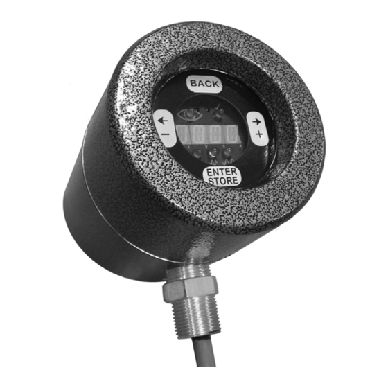
U2 Combination Viewing Head and
Signal Processors
INTRODUCTION
The Honeywell U2 flame monitoring system combines sensing
and processing in one package. The U2 is available in several
models to provide different options. Each model includes one,
two or three sensors which share the same optical axis. The
U2 can be connected either through a detachable connector
or a pipe fitting for installations with conduit. Refer to the table
below for model numbers and options.
APPLICATION
Each sensor in the U2 has a different response which is
suitable for certain applications.
The UVTRON tube detector has a peak response at 210 nm
and is primarily for gas flame monitoring. This UV detector
using pulse technology is the best for low NOx gas burners
and where a solid state sensor, using flicker technology, does
not provide satisfactory results.
The solid state UV photodiode has a peak response at 310
nm. This sensor is suitable for gas, oil and coal. The principle
of flame monitoring is flicker frequency based. User selectable
high pass filters are used to reject signals that are from
background radiation.
The solid state IR photodiode has a peak response at
1400 nm. This sensor is suitable for low NOx oil and coal
burners, low excess air oil burners, and burners with a limited
view from a windbox front plate. The principle of flame
monitoring is flicker frequency based. User selectable high
pass filters are used to reject signals that are from background
radiation.
Introduction .......................................................................
Application ........................................................................
Specifications ...................................................................
Approvals ..........................................................................
Installation ........................................................................
Accessories ......................................................................
Operation ..........................................................................
Troubleshooting ................................................................
Communicating Through Modbus ....................................
Manual Setup ................................................................... 13
Automatic Setup ............................................................... 14
Maintenance ..................................................................... 15
Safety Manual ................................................................... 22
Safety Function of the Uniscan 2 ......................... 23
Proof Test Procedure ........................................... 23
Proof Test Interval ................................................ 23
Product Decommissioning ................................... 24
USER MANUAL
Contents
1
1
2
3
3
5
6
9
9
66-2071-02
Advertisement
Table of Contents

Related Manuals for Honeywell U2


Summary of Contents for Honeywell U2
-
Page 1: Table Of Contents
Signal Processors USER MANUAL APPLICATION Each sensor in the U2 has a different response which is suitable for certain applications. The UVTRON tube detector has a peak response at 210 nm and is primarily for gas flame monitoring. This UV detector... - Page 2 U2-1016-PF U2-1018 U2-1018-PF * The U2-1010-PF-050 has a 50-ft (15m) pigtail and the U2-1010-PF-100 has a 100-ft (30m) pigtail. 3. Ten (10) flicker frequency filters for solid state UV and IR All models include the following: 1. Electronic check (no mechanical shutter) for self-check sensor (model dependent) of the system.
- Page 3 Wiring U2 models with a pipe fitting have slightly different wiring than models with a removable connector. Refer to the table and diagram below for wire function, connection, and comments. Honeywell C12S cable colors are referenced for the Connector (CAB22) wires.
- Page 4 0, connect the file input wire to ground. Pressure NOT USED The U2 lens will withstand 500 psi. If the U2 will be exposed to YELLOW WHITE pressures over 500 psi, contact your distributor or Honeywell for guidance.
- Page 5 U2 lens free of dirt and debris. The air As an example of proper sighting challenges, detecting flame supply must be clean, free of oils and water, and preferably in a sulfur recovery unit can present a challenge for IR flame cool.
-
Page 6: Operation
User Interface IR and UV Detectors A touch wheel located on the back of the U2 is used for operator interface. The configuration menu is simple and easy See Table 1 on page 2 to determine which sensors are active to follow. - Page 7 Fig. 2. User interface menu overview. NOTE: If sensor is not available in your model, then no menu item will exist for sensor setting. See Table 1 on page 2 to determine which sensors are active in your U2 model. Temperature Gain SSUV Displays the processor temperature.
- Page 8 File NOTE: If the display shows “9999”, it can also indicate The U2 is able to store up to 8 different file configurations (file0 saturation of the UVSS and/or IR sensor. If the – file7). Settings that are stored include: UVT gain, SSUV...
-
Page 9: Troubleshooting
If saturation of the IR or SSUV sensor persists for greater than must be changed before modbus communication can take 1 second, the flame Relay will open, and the U2 will lock out place. For applications where large quantities of U2 are used,... - Page 10 Parity setting. Only affects RS-485 communication, not IRDA. 8 bit 0-no parity (default), 1=odd parity, 2=even parity 40087 ADDRESS Modbus address of U2 used by RS-485 and IRDA. Each flame 8 bit monitor must have a unique address. 40092 NUMFILES User set limit on the number of files able to be used.
- Page 11 GROUND SHIELD DRAIN WIRE NOTES: SELECT THE APPROPRIATE DIP SWITCH SETTINGS FOR RS-485 COMMUNICATION PER THE VENDOR’S INSTRUCTION SHEET. SOFTWARE DRIVERS MAY BE DOWNLOADED FROM B&B ELECTRONICS’ WEBSITE. M33862 Fig. 4. Wiring of RS422/485 to USB Converter to U2. 66-2071—02...
- Page 12 U2 COMBINATION VIEWING HEAD AND SIGNAL PROCESSORS 1 (25) NPT 1(25) 5-3/32 (130) CONNECTION 4-19/32 (118) 3/4 (19) NPT 2-29/32 (73) CONNECTION M34431 Fig. 5. U2 dimensions. 66-2071—02...
-
Page 13: Manual Setup
13. If selected setting is not correct to recognize oil igniter d. Check that the U2 recognizes the pilot and main flame, adjust IR gain and filter. flames. If the flame signal is below Flame On 14. -
Page 14: Automatic Setup
“File Select” 0/ files for obtaining the required discrimination. 24 Vdc input on the U2. The third file must be selected via a Modbus RTU interface. Refer to AUTOMATIC SETUP Table 3 and the “FILE”... -
Page 15: Maintenance
5. Wait as instructed by the display. A monthly sensitivity check is suggested to determine if the UV tube sensor's life is terminated. The reading of the U2 After the burner is in service and boiler load is above 90%, digital display should be compared to the initial reading of the perform the following for discrimination tests and adjustments. - Page 16 U2 COMBINATION VIEWING HEAD AND SIGNAL PROCESSORS UV RADIATION ZONE UV VIEWING HEAD SIGHTED ON UV ZONE BURNER NOZZLE CENTERLINE M33286 Fig. 7. UV viewing head location. NO. 1 FLAME NO. 2 FLAME ENVELOPE ENVELOPE VIEWING HEAD VIEWING HEAD BURNER NOZZLE NO. 1 BURNER NOZZLE NO.
- Page 17 “Y” or “T” in between the locking coupler and the sight pipe to reduce conducted heat and to keep the sight pipe and U2 lens clean of debris and dirt. Refer to the Mounting and Sighting section on purge air requirements.
- Page 18 (0000 0100) 1=on, 0=off Display (0000 1000) 1=on, 0=off Wheel (0001 0000) 1=on, 0=off 40020 HIGHTEMP Stores the highest internal temperature (ºC only) the U2 8 bit has achieved (read only) 40060 SERIALNUM Factory set identification number (read only) -32768...
- Page 19 0 to 127 as you move your finger clockwise around the wheel. The output is 232 when no touched. Write a 1 to re-calibrate the U2. Other numbers will give an error. WARNING: DO NOT TOUCH THE WHEEL WHILE RE-CALIBRATING.
- Page 20 Table 5. Extended Modbus Register Map. (Continued) Register Name Description Minimum Maximum Size 40189 PAGECNT Counts every fourth time power is reset to the U2 (read -32768 32767 16 bit only) 40190 IRFILTCOUNT IR filter selection for filter 0 (read only)
- Page 21 U2 COMBINATION VIEWING HEAD AND SIGNAL PROCESSORS Table 5. Extended Modbus Register Map. (Continued) Register Name Description Minimum Maximum Size 40291 IRSAVEGAIN Saved gain of the IR sensor from the current file 8 bit determined by the auto gain function (read only)
-
Page 22: Safety Manual
U2 COMBINATION VIEWING HEAD AND SIGNAL PROCESSORS SAFETY MANUAL Uniscan 2 Product Declaration FIT FOR USE IN A Low Demand SAFETY APPLICATION Models: 1010, 1012, 1016, 1018, 1010-PF, 1012-PF, 1016-PF, 1018-PF λ λ λ Models SIL HFT 1010/1010PF >99% 1.54 X10 1.08 X10... -
Page 23: Safety Function Of The Uniscan 2
The following diagram for the U2-1010 shown for example, All Uniscan 2 signal processor models contain a Self Check presents the dependence of the PFD... -
Page 24: Product Decommissioning
FFRT (Flame Failure Response Time) has Product Decommissioning elapsed. 5. Measure the current draw of the U2 and ensure it is less When required, decommissioning of the Uniscan 2 than 120 mA. flamescanner should be performed in accordance with requirements of the overall safety system.
Need help?
Do you have a question about the U2 and is the answer not in the manual?
Questions and answers