Table of Contents
Advertisement
Quick Links
Training Guide
Publication Number E2433-97034
First Edition, November 1997
For Safety information, Warranties, and Regulatory
information, see the pages behind the Index.
© Copyright Hewlett-Packard Company 1992–1997
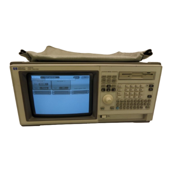
Training Kit for
HP 1660/70 Series Logic
Analyzers
Get other manuals https://www.bkmanuals.com
Advertisement
Table of Contents

Related Manuals for HP 1670 Series


Summarization of Contents
HP Logic Analyzer Training Guide
Product Identification
Identifies the document as the "Training Kit for HP 1660/70 Series Logic Analyzers".
Getting Started: Initial Setup
Start Here Procedure
Initiates the setup process, guiding initial connections and analyzer state.
Introduction to Logic Analysis
Running the Analyzer
Describes the final step to run the analyzer and view its output, showing an example output.
Overview of Logic Analysis Concepts
Required Materials
Lists the necessary hardware and software to complete the training exercises.
Training Guide Structure
Chapter Content Summary
Provides a brief overview of the topics covered in each chapter of the training guide.
Chapter 1: Analyzer and Measurement Process
Learning Objectives
Lists the skills and knowledge participants will gain from this chapter.
Front Panel Navigation and Interaction
Explains how to navigate and interact with the analyzer's front panel controls and menus.
Measurement Process Steps
Details the sequence of steps involved in making a basic measurement with the analyzer.
Chapter 2: Introduction to Timing Analysis
Understanding Timing Analysis Principles
Defines timing analysis, its principles, and differences from oscilloscopes.
Chapter Objectives
Lists the specific tasks covered in the timing analysis chapter.
Chapter 2 Prerequisites
Details pre-exercise steps including configuration, pod connection, and jumper settings.
Configuring Timing Mode
Guides the user on how to set the analyzer to timing mode for analysis.
Renaming Labels for Clarity
Explains how to rename labels to improve the clarity and meaning of captured data.
Assigning Channels to Labels
Describes how to assign active bits from a pod to a specific label for data capture.
Defining Timing Trigger Terms
Details how to define trigger terms to specify conditions for capturing timing data.
Configuring Timing Trigger Specifications
Guides the user in setting up the trigger parameters and duration for timing analysis.
Executing Trigger and Analyzing Waveforms
Explains how to run the analyzer, trigger based on defined terms, and examine the resulting waveform.
Chapter 3: Introduction to State Analysis
Understanding State Analysis Principles
Defines state analysis, its principles, and differences from timing analysis.
Chapter Objectives
Lists the specific tasks participants will learn in the state analysis chapter.
Chapter 3 Prerequisites
Details pre-exercise steps including configuration loading, pod connection, and jumper settings for state analysis.
Configuring State Mode
Guides the user on setting the analyzer to state mode for state analysis.
Configuring the State Clock
Explains how to set the state clock source and edge for accurate data sampling.
Renaming State Labels
Describes how to rename labels for state data, similar to timing data.
Assigning Channels for State Analysis
Details assigning channels for state analysis, mirroring the process for timing analysis.
Defining State Trigger Terms
Explains how to define terms for state trigger conditions using hexadecimal values.
Configuring State Trigger Level 1
Sets up the first level of the state trigger sequence for data storage.
Configuring State Trigger Level 2
Sets up the second level of the state trigger sequence to store data after the trigger pattern.
Running State Analyzer and Viewing Data
Guides the user to run the state analyzer and view/modify the captured state listing.
Creating State Data Symbols
Explains how to define symbols to represent hexadecimal values for easier interpretation of state data.
Creating More State Symbols
Demonstrates creating additional symbols for different hexadecimal values in state listings.
Viewing State Data with Symbols
Shows how to select and view defined symbols in the state listing for better data readability.
Chapter 4: Comparing State Traces
Understanding State Comparison Feature
Explains the state compare feature for verifying system execution by comparing listings.
Chapter Objectives
Lists the tasks involved in performing state trace comparisons and error identification.
Chapter 4 Prerequisites
Details pre-exercise steps including configuration loading, pod connection, and jumper settings for comparison.
Verifying Configuration for State Compare
Guides the user to check analyzer settings for state compare mode.
Configuring State Trigger for Comparison
Sets up the state trigger specification to capture data for comparison, focusing on post-trigger data.
Executing Trace and Viewing Listing
Runs the analyzer with the new trigger and views the resulting state listing without pretrigger data.
Saving Listing as Reference
Copies the acquired state listing to serve as a reference for future comparisons.
Modifying Jumper for Data Variation
Changes a jumper setting to alter acquired data for comparison with the reference listing.
Acquiring New Data and Finding Differences
Acquires new data, compares it to the reference, and identifies differences using the Find Error feature.
Chapter 5: Mixed Mode Analysis
Understanding Mixed Mode Correlation
Explains mixed mode analysis, combining state and timing data for detailed problem capture.
Chapter Objectives
Lists tasks for performing mixed mode analysis and correlating data.
Chapter 5 Prerequisites
Details pre-exercise steps including jumper settings, configuration loading, and pod connections for mixed mode analysis.
Connecting Timing Analyzer Pods
Guides connection of the timing analyzer pod and associated probe leads to the training board.
Configuring Dual Analyzer Modes
Sets up the analyzer to run simultaneously in both state and timing modes for correlation.
Renaming and Assigning Labels for Timing Data
Renames labels and assigns channels for timing data, and enables TCOUNT label in waveform menu.
Clearing Timing Trigger Settings
Clears the timing analyzer trigger specification to a "don care" state for synchronization.
Enabling Time Stamp Correlation
Enables time stamping for state data, allowing correlation with timing analysis displays.
Arming Timing Analyzer via State Analyzer
Configures the state analyzer to arm the timing analyzer for synchronized data capture.
Displaying Correlated State and Timing Data
Displays combined state and timing data with markers to visualize time correlation.
Chapter 6: Advanced State Triggering
Chapter Objectives
Lists tasks for utilizing multi-level triggering capabilities of the state analyzer.
Chapter 6 Prerequisites
Details pre-exercise steps including configuration loading and pod connections for advanced triggering.
Configuring State Mode for Advanced Triggering
Sets the analyzer to state mode for advanced triggering exercises.
Defining Multiple State Trigger Terms
Defines multiple trigger terms with decimal values for sequential state triggering.
Defining Range and Single Value Terms
Defines a trigger term for a range of values and a separate term for a single value.
Adding State Trigger Sequence Levels
Adds multiple sequence levels to build a complex trigger specification.
Configuring State Trigger Level 1 (Find Term 'a')
Sets up Level 1 to find and store only term "a" the first time it occurs.
Configuring State Trigger Level 2 (Range and Term 'e')
Sets up Level 2 to store range values and find term "e".
Configuring State Trigger Level 3 (Find Term 'b')
Sets up Level 3 to find and store only term "b" the first time it occurs.
Configuring State Trigger Level 4 (Combination Term)
Defines a combination trigger term using boolean logic (OR) of multiple previous terms.
Verifying Advanced Trigger Specification
Reviews the configured multi-level trigger specification to ensure accuracy.
Executing Advanced Trigger and Viewing Data
Runs the analyzer with the advanced trigger and views the captured data in decimal format.
Chapter 7: Using the Oscilloscope
Oscilloscope Operations Overview
Introduces using the built-in oscilloscope for waveform analysis and measurements.
Chapter Objectives
Lists the specific oscilloscope functions that will be covered in the chapter.
Chapter 7 Prerequisites
Details pre-exercise steps including configuration loading, pod connection, and jumper settings for oscilloscope usage.
Connecting Oscilloscope Probe
Guides the connection of the oscilloscope probe to the analyzer and training board test points.
Displaying Waveforms with Autoscale
Uses the Autoscale feature to automatically set up the oscilloscope display for viewing waveforms.
Optimizing Display Space
Deletes unused channels from the display to maximize space for active waveforms.
Navigating Waveforms
Explains how to use s/Div and Delay fields to zoom and scroll through displayed waveforms.
Manual Clock Period Measurement
Guides manual measurement of clock period using X and O markers on the waveform.
Automatic Clock Period Measurement
Utilizes the Auto Measure function for automatic measurement of clock period parameters.
Measuring Voltage with Markers
Shows how to use voltage markers (Va, Vb) to measure specific voltage levels on the waveform.
Chapter 8: Triggering Oscilloscope with Timing Analyzer
Correlating Timing and Oscilloscope Triggers
Explains using timing analyzer to trigger oscilloscope for time-correlated glitch capture.
Chapter Objectives
Lists tasks for using timing analyzer to trigger oscilloscope and capture glitches.
Chapter 8 Prerequisites
Details pre-exercise steps including configuration loading and pod connections for oscilloscope triggering.
Configuring Glitch Detection Jumper
Sets the glitch jumper to ON to enable glitch detection on bit 7.
Connecting Oscilloscope Probe for Glitch Detection
Connects the oscilloscope probe to the "Glitch" test point for glitch analysis.
Displaying Glitch Waveform with Autoscale
Uses Autoscale to display the glitch waveform, with an arbitrary trigger point.
Synchronizing Oscilloscope Trigger
Sets the oscilloscope trigger to "Immediate" to capture data right after the timing analyzer triggers.
Activating Timing Analyzer Mode
Sets Analyzer 1 to timing mode to capture glitch data.
Configuring Timing Format for Glitch Capture
Sets timing acquisition mode to "Glitch" and enables the TCOUNT label for glitch analysis.
Defining Timing Trigger for Glitches
Defines a timing trigger term ("Edge 1") to detect glitches on a specific bit.
Configuring Timing Trigger Specification for Glitches
Sets up the timing trigger specification to trigger on the first occurrence of the defined "Edge 1" glitch.
Arming Oscilloscope with Timing Analyzer
Arms the oscilloscope using the timing analyzer's trigger to capture the glitch.
Displaying Oscilloscope Data with Timing Waveforms
Inserts the oscilloscope waveform into the timing waveform display for correlation.
Capturing the Glitch in Mixed Mode
Captures the glitch using both timing analyzer and oscilloscope, noting slight delay.
Aligning Glitch Displays
Measures time delay and uses skew feature to align glitch displays from oscilloscope and analyzer.
Chapter 9: Using the Pattern Generator
Pattern Generator Overview
Explains the pattern generator's role in providing programmable digital output for testing.
Chapter Objectives
Lists tasks for programming the pattern generator and viewing its output.
Chapter 9 Prerequisites
Details pre-exercise steps including configuration loading, pod connection, and jumper settings for pattern generator usage.
Connecting Pattern Generator Hardware
Guides the connection of the pattern generator output pod to the TTL Data Pod and training board.
Activating Timing Analyzer for Pattern Output
Sets Analyzer 1 to timing mode to observe the pattern generator output.
Renaming Labels for Pattern Generator Data
Renames labels to represent pattern generator data and turns off the TCOUNT label.
Assigning Channels for Pattern Generator Output
Assigns channels of Pod A1 to the PATGEN label for capturing pattern generator output.
Configuring Timing Trigger for Pattern Occurrence
Sets a timing trigger term to detect the occurrence of a '1' from the pattern generator.
Displaying Pattern Generator Data
Adds the PATGEN label to the waveform display to show the pattern generator's output.
Configuring Pattern Generator Format
Configures the pattern generator format menu, assigning Pod B4 bits to PATGEN.
Assigning Pod Bits for Pattern Output
Completes the assignment of Pod B4 bits to the PATGEN label for output.
Programming the "Walking Ones" Pattern
Programs the pattern generator to output a "walking ones" sequence in binary format.
Completing the "Walking Ones" Program
Adds subsequent lines to the program to complete the "walking ones" sequence.
Running Pattern Generator and Viewing Output
Starts the pattern generator and views the "walking ones" pattern on the timing analyzer waveform display.
Stopping the Pattern Generator
Stops the pattern generator to free up CPU resources for other exercises.
Chapter 10: Introduction to Inverse Assembly
Understanding Inverse Assembly
Explains how an inverse assembler translates captured data into microprocessor instructions.
Chapter Objectives
Lists tasks for loading and using inverse assembly features.
Loading Inverse Assembler and Sample Listing
Loads configuration files and sample listings for inverse assembly simulation.
Viewing Inverse Assembly Labels
Explains the ADDR, DATA, and STAT labels used by the inverse assembler for translating binary data.
Viewing Assembly Listing
Shows how to view captured data in mnemonic form and realign assembler if out of sync.
Filtering Inverse Assembly Data
Filters captured data to display specific instruction types, like jumps, for code flow analysis.
Chapter 11: Jumpers and Configuration Files
Jumper Settings Overview
Provides an overview of jumper functions and settings for different chapters.
Procedure for Setting Jumpers
Details the physical steps for setting jumpers on the training board according to table settings.
Configuration File Management
Lists available configuration files and recommends loading procedures for exercises.
Procedure for Loading Configuration Files
Provides step-by-step instructions for loading configuration files onto the analyzer.
Chapter 12: Logic Analyzer Training Board Reference
Training Board Power Source
Explains how the training board receives power from logic analyzer pods.
Training Board Circuit Description
Describes the circuit components and functionality of the training board, including the ripple counter.
Training Board Jumper Functions
Details the functions of the Glitch, CLK1, and CLK2 jumpers on the training board.
Training Board Schematic Diagram
Provides a schematic diagram of the logic analyzer training board circuitry.
Safety Information
General Safety Precautions
Provides essential safety warnings regarding electrical shock, grounding, and instrument operation.
Safety Symbols and Indicators
Explains the meaning of standard safety symbols and hazard indicators used in the manual.
Product Warranty and Support
Product Warranty Terms
Outlines the product warranty terms, limitations, and exclusions.
Customer Assistance and Manual Information
Provides information on obtaining customer assistance and details about the manual's edition.
Need help?
Do you have a question about the 1670 Series and is the answer not in the manual?
Questions and answers