Table of Contents
Advertisement
Advertisement
Table of Contents

Related Manuals for F.W. Bell 5280


Summary of Contents for F.W. Bell 5280
- Page 1 Manual 095-415200-01 Rev. A OECO, LLC All rights reserved.
-
Page 2: Table Of Contents
Table of Contents Section - 3 Operating Instructions Section -1 Introduction OPERATOR SAFETY ..............UNDERSTANDING FLUX DENSITY........INSTRUMENT PREPARATION ..........MEASUREMENT OF FLUX DENSITY ........OPERATING FEATURES………..........PRODUCT DESCRIPTION ............ POWER-UP ................APPLICATIONS ..............POWER-UP SETTINGS ............LOW BATTERY CONDITION ............ HOME SCREEN ……………………………………………...……. - Page 3 Table of Contents, Cont. List of Illustrations Section - 4 Remote Operation Figure 1-1 Flux Lines of a Permanent Magnet......Figure 1-2 Hall Generator............USB INTERFACE CONNECTION …......………… Figure 1-3 Hall Probe Configurations........REMOTE COMMAND STANDARDS …………....….. Figure 2-1 Standard Transverse Probe........COMMAND FORMAT ……......……………...…..
- Page 4 Statement regarding improvements to 5200 Series Gaussmeters The 5200 Series Gauss / Tesla Meters have improved user interface with the same accuracy, measurement features, and digital signal processing technology. Summary of changes: • 4.3” LCD touch-screen with a new user interface.
-
Page 5: Section -1 Introduction
Section 1 Introduction UNDERSTANDING FLUX DENSITY Magnetic fields surrounding permanent magnets or electrical conductors can be visualized as a collection of magnetic flux lines, lines of force existing in the material that is being subjected to a magnetizing influence. Unlike light, which travels away from its source indefinitely, magnetic flux lines must eventually return to the source. -
Page 6: Measurement Of Flux Density
Section 1 Introduction MEASUREMENT OF FLUX DENSITY A device commonly used to measure flux density is the Hall generator. A Hall generator is a thin slice of a semiconductor material to which four leads are attached at the midpoint of each edge, as shown in Figure 1-2. Figure 1-2 Hall Generator A constant current (Ic) is forced through the material. - Page 7 The sensitive area of the Hall generator is generally defined as the largest circular area within the actual slice of the material. This active area can range in size from 0.2 mm (0.008”) to 19 mm (0.75”) in diameter. Often the Hall generator assembly is too fragile to use by itself so it is often mounted in a protective tube and terminated with a flexible cable and a connector.
-
Page 8: Product Description
PRODUCT DESCRIPTION The MODEL 5270 / 5280 GAUSS / TESLAMETER is a portable instrument that utilizes a Hall probe to measure magnetic flux density in terms of gauss, tesla or ampere/meter. The measurement range is from 0.01 mT (0.1 G or 0.01 kA/m) to 3.000T (30.00 kG or 2388 kA/m) for the 5280, and 2.000T (20.00 kG or 1592 kA/m) for the 5270. - Page 9 Section 2 Specifications 5270 5280 Ranges: Ultra Low Probe 200 G 300 G 2 kG 3 kG High 20 kG 30 kG Resolution: Ultra Low Probe 1 mG 1 mG 0.1 G 0.1 G 1.0 G 1.0 G High 10 G 10 G Specifications continued on next page...
- Page 10 SPECIFICATIONS, MODEL 5270 & 5280 GAUSS / TESLAMETER without probe, 23 ±3ºC, RH <85% Probe accuracy must be added to meter accuracy to determine Accuracy, ±% of Reading ± counts 5270 5280 overall accuracy DC MODE, Low Range: 1.25+ 4 0.8 + 4 Warmup Time to Rated Accuracy: 15 minutes...
-
Page 11: Lithium-Ion Battery
Description: The 5200 series Gauss/Tesla meter runs on a rechargeable lithium-ion battery with a rated discharge capacity of 3900 mAh. Depending on usage (primarily screen-brightness), a fully charged battery should be capable of powering a 5200 series Gauss/Tesla meter for 8-15 hours. -
Page 12: Standard Transverse Probe
** Prior to late 2006 Transverse Probe Stems were rigid glass epoxy, .150 x .040”. From 2006 to 2014 they were polypropylene, .158 x .045”. *** Not available for purchase. Existing STB1X-0201 probes can be used with 5200 series meters. -
Page 13: Standard Axial Probe
STANDARD AXIAL PROBE Model Number: (5280): SAD18-1904 5280 gaussmeter probes (5270): SAH17-1904 SAD18-1904 4" Axial Probe SAD18-1902 2" Axial Probe Flux Density Range: (5280): 0 to ±30 kG (0 to 3 T) (5270): 0 to ±20 kG (0 to 2 T) 5270 gaussmeter probes SAH17-1904 4"... -
Page 14: Low Field Axial Probe
LOW FIELD AXIAL PROBE Model Number: MOS51-3204 Flux Density Range: ±1G (100 µT) DC or peak AC Corrected Linearity: ±0.75% of Reading Frequency Bandwidth: 0 to 700 Hz (-3dB) Offset change with Temperature: ±0.02mG / ºC (typical) Accuracy change with Temperature: 0.001 % / ºC (typical) Operating Temperature Range: 0 to +75ºC (+32 to +167°F) Storage Temperature Range: -25 to +75ºC (-13 to +167°F) Figure 2-3... -
Page 15: Zero Flux Chamber
ZERO FLUX CHAMBER MODEL NUMBER: YA111 CAVITY DIMENSIONS: Length: 50.8 mm (2”) Diameter: 8.7 mm (0.343”) ATTENUATION: 80 dB to 30 mT (300 G) PURPOSE: To shield the probe from external magnetic fields during the ZERO or RELATIVE operations. Figure 2-4 Zero Flux Chamber... -
Page 16: Section - 3 Operating Instructions
Section 3 Operating Instructions OPERATOR SAFETY 1 This symbol appears on the instrument and probe. It Do not allow the probe to come in contact with any refers the operator to additional information contained in voltage source greater than 30 Vrms or 60 Vdc this instruction manual, also identified by the same symbol. - Page 17 OPERATOR SAFETY 2 Battery Safety ATTENTION Failure to follow the guidelines in this document may result in damaged equipment and/or personal injury. Use the battery for its intended application only. IMPORTANT Do not: • Open, puncture or crush the battery •...
-
Page 18: Instrument Preparation
INSTRUMENT PREPARATION 1) Remove screen protector from the touch screen. 2) Plug in the USB cable into the meter. 3) Plug the other end of the USB cable into the power adapter and apply power to charge the battery fully (approximately 2 hours). 4) Install the probe by matching the keyway in the connector to that in the mating socket in the meter. -
Page 19: Operating Features
OPERATING FEATURES Keypad On/Off button ————————————————————————————————— Enter button —————————————————————————————————— Navigation arrow buttons, left —————————————————————————— Navigation arrow buttons, right —————————————————————————— Navigation arrow buttons, up ———————————————————————————— Navigation arrow buttons, down ——————————————————————————— The On/Off button and the Enter button can be used with a ‘short’ press or a ‘long’ press. To implement a ‘short’ press, hold the button down for less than one second before releasing. -
Page 20: Power-Up
POWER-UP Power ON To turn the unit ON, press————————————————————————————————————————————— Power OFF To turn the unit OFF, for three seconds press ———————————————————————————————————— Alternatively, short press ————————————————————————————————————————————— then select ———————————————————————————————————————————————— To cancel the power off operation, select —————————————————————————————————————— When battery power is used for the first time, momentarily apply USB power to the meter to activate the battery. This will need to be done any time the battery is disconnected and re-installed. -
Page 21: Power-Up Settings
POWER-UP SETTINGS The meter permanently saves certain aspects of the instrument’s setup and restores them the next time the meter is turned on. The conditions that are saved are: RANGE setting (including AUTO range) MODE (AC or DC) UNITS of measure (gauss, tesla or ampere/meter) ANALOG OUTPUT function Meter settings (brightness, dark mode, audio, time &... -
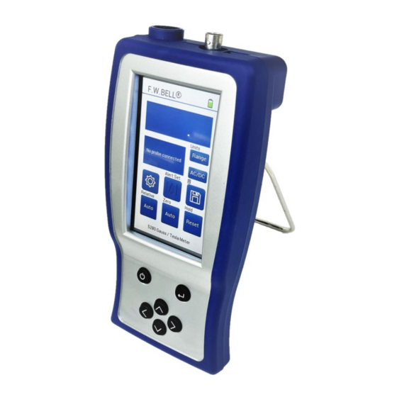
Page 22: Home Screen
Home Screen 1. Measurement 2. Information Box Status on current settings Messages 3. Settings pages 4. Relative (cancel known fields) Auto/Manual displayed ‘short press’ start relative operation ‘long press’ to relative setting page 5. Zero (cancel ambient fields) Auto/Manual displayed ‘short press’... -
Page 23: Meter Settings
Meter Settings Setting Pages To access the settings pages, press ———————————————————————————————————— To move between pages, press ———————————————————————————————— To go back to the home screen, press ——————————————————————————————————— Setting page number can be seen in the upper left corner ————————————————————————— The highlighted larger dot indicates the page number 5280 Only Figure 3-9... -
Page 24: Brightness
Brightness On settings page 3, the brightness screen indicator is —————————————————— The brightness can be adjusted using the brightness indicator. Press the anywhere on the bar to adjust the screen to that brightness. Alternatively, the keypad can be used to navigate to the brightness indicator and use the left/right arrows to adjust. The battery will last longer with a lower brightness setting. -
Page 25: Date And Time
Date and Time On settings page 3, enter the Date & Time settings page by pressing —————————————————————— To set the Date & Time, use the arrow and +/- buttons ———————————————————————— To save the current selection, press ————————————————————————————————————————— The arrows control the position of the underline. The value that is underlined can be adjusted by using the plus and the minus buttons. The D/M/Y button can be used to cycle through the date formats: D/M/Y, M/D/Y. -
Page 26: Languages
Languages In settings page 4, toggle between languages by pressing —————————————————————————— Pushing the language button will display a message that indicates the only language currently supported is English. Touch Screen Calibration In settings page 4, start the screen calibration by pressing —————————————————————... -
Page 27: Error Buffer
Error Buffer In settings page 4, view the error buffer by pressing —————————————————————————————— The Error Buffer will display error codes if an error does occur. The meter will list the 12 most recent errors since powering on. The error codes will not automatically be erased if the error is no longer present. -
Page 28: Ac Or Dc Measurement Selection
AC OR DC MEASUREMENT SELECTION To toggle between AC and DC Mode, press on the home screen ——————————————————— Alternatively, press ———————————————————————————————————————————————— To navigate to setting page 1, press ———————————————————————————————— To toggle AC/DC modes, press ——————————————————————————————— To return to normal operation, press —————————————————————————————————————... -
Page 29: Range Selection
RANGE SELECTION To select Auto Range or a fixed Range, press on the home screen ————————————————————————— Press Range until the desired range is selected and shown in the info box ————————————————— Alternatively, press ———————————————————————————————————————————————— To navigate to setting page 1, press —————————————————————————————————... -
Page 30: Hold Mode Selection
HOLD MODE SELECTION To select Min, Max, Peak, Off, press and hold on the home screen ——————————————————————————— Press Range until the desired range is selected and shown in the info box —————————————————— Alternatively, press ———————————————————————————————————————————————— To navigate to setting page 1, press —————————————————————————————————... -
Page 31: Min/Max Hold Usage
MIN / MAX HOLD USAGE See the SPECIFICATIONS section for response time information. The MAX HOLD function holds the reading that is arithmetically greater than all previous readings. The MIN HOLD function holds the reading that is arithmetically less than all previous readings. These modes are useful in determining the maximum or minimum value of magnetic events that occur over a period of time. -
Page 32: Zero Function
ZERO FUNCTION “Zeroing” the probe and meter is one of the most important steps to obtaining accurate dc flux density measurements. The ideal Hall generator produces zero output in the absence of a magnetic field, but actual devices are subject to variations in materials, construction and temperature. Therefore, most Hall generators produce some output even in a zero field. -
Page 33: Automatic Zero Function
AUTOMATIC ZERO FUNCTION To start the AUTO ZERO operation when and AUTO is already selected, press on the home screen ———————————— To select AUTO ZERO from the ZERO settings page, press and hold on the home screen ———————————————— Alternatively, press ————————————————————————————————————————————————... - Page 34 AUTOMATIC ZERO FUNCTION The meter provides two methods to zero the probe. The first is completely automatic. Prepare the probe for zeroing, then start the automatic zeroing. The screen will say “Processing” while the meter zeros, and afterwards the meter will display approximately zero as the current reading.
-
Page 35: Manual Zero Function
MANUAL ZERO FUNCTION To select MANUAL ZERO from the ZERO settings page, press and hold on the home screen ——————————————— Alternatively, press ———————————————————————————————————————————————— To navigate to setting page 2, press ————————————————————————————————— To enter the ZERO settings page, press ———————————————————————————— To select MANUAL ZERO in settings page, press until button displays MANUAL ————————————————————... - Page 36 MANUAL ZERO FUNCTION The second zeroing method is a manual adjustment. This feature also allows the user to set the “zero” point to something other than zero, if desired. Position the probe for zeroing, then start a manual ZERO operation. The screen will display the actual DC flux density readings. The meter will select the lowest range regardless of which range was in use prior to selecting the ZERO function.
-
Page 37: Relative Mode
RELATIVE MODE The RELATIVE mode allows a specific flux density value to be subtracted from all incoming readings. When the RELATIVE mode is active, all incoming readings are "relative" to an offset selected by the user. For example, if the displayed value is +100 gauss when RELATIVE mode is activated, and the flux density at the probe changes to +150 gauss the displayed value will be +50.0 gauss. -
Page 38: Automatic Relative Mode
AUTOMATIC RELATIVE MODE To start the AUTO RELATIVE when and AUTO is already selected, press on the home screen —————————————— To select AUTO RELATIVE from the RELATIVE settings page, press and hold on the home screen ————————————— Alternatively, press ———————————————————————————————————————————————— To navigate to setting page 2, press —————————————————————————————————... - Page 39 MANUAL RELATIVE FUNCTION To select MANUAL RELATIVE from the RELATIVE settings page, press and hold on the home screen ——————————— Alternatively, press ———————————————————————————————————————————————— To navigate to setting page 2, press ————————————————————————————————— To enter the RELATIVE settings page, press —————————————————————————— To select MANUAL RELATIVE in settings page, press until button displays MANUAL ——————————————————...
-
Page 40: Measurement Log
Measurement Log To save a measurement, press on the home screen ————————————————————————————————— Short press to save the current measurement Long press to view the saved measurements The meter can save the current measurement along with the date and time by pressing the save button. The measurement log can be viewed by pressing and holding the save button. -
Page 41: Alert Ranging Mode
ALERT RANGING MODE To select ALERT SET from the ALERT SET settings page, press and hold on the home screen —————————————— Alternatively, press ———————————————————————————————————————————————— To navigate to setting page 2, press —————————————————————————————— To enter the ALERT SET settings page, press —————————————————————————... - Page 42 ALERT RANGING MODE In the Alert Ranging mode, an audible beep can be set based on a user defined range. The audible beep can be enabled when in range, enabled when out of range, or disabled. When the measurement meets the audio range criteria, the meter will send out a continuous beep until the measurement transitions outside of the audio criteria range or until the Alert Set feature is set to off.
-
Page 43: Analog Output Function
ANALOG OUTPUT FUNCTION To enable and disable ANALOG OUTPUT operation, press —————————————————————————————— To navigate to setting page 2, press ———————————————————————————————— To ANALOG OUTPUT to ON, press to show the power icon filled with white ———————————— To ANALOG OUTPUT to OFF, press to show the power icon empty ———————————————... - Page 44 When both the ANALOG OUTPUT and AUTO RANGE features are active, the following condition can occur: Suppose the present range is 3 kG and the present reading is +2.8 kG. The analog output will be +2.8 VDC. The signal then increases to +3.2 kG, which would force an automatic change to the 30 kG range setting.
-
Page 45: Sources Of Measurement Errors
SOURCES OF MEASUREMENT ERRORS When making flux density measurements, there are several conditions that can introduce error: 1) Operating the meter while the battery symbol shows low (battery symbol has a small amount of red at the bottom). Instrument specifications are not guaranteed when a low battery condition exists! 2) Failure to zero the error signals from the meter, probe, and nearby sources of magnetic interference. -
Page 46: More Details On Ac Mode Operation
6) Flux density can vary considerably across the pole face of a permanent magnet. This can be caused by internal physical flaws such as hairline cracks or bubbles, or an inconsistent mix of materials. Generally, the sensitive area of a Hall generator is much smaller than the surface area of the magnet, so the flux density variations are very apparent. -
Page 47: More Details On Dc Mode Operation
An AC reading, being a true RMS value, has no polarity. However, when using the RELATIVE function in AC mode, a negative value may be displayed. A negative AC reading means that the present reading is less than the RELATIVE value. An unsigned value means the present reading is greater than or equal to the RELATIVE value. -
Page 48: Battery Removal
Battery Removal Only remove the battery if it is safe to do so. Be sure the battery is not too warm to touch and there are no obvious signs of damage. Step 1: Remove the back battery cover by pressing the raised bumps STEP 2 towards the bottom of the meter. -
Page 49: Battery Installation
Battery Installation Only install the battery if it is safe to do so. Be sure the battery is not too warm to touch and there are no obvious signs of damage. Ensure the battery is installed with the correct polarity and handle the battery carefully. Step 1: With the battery cover off, make sure the ribbon is sitting across the empty battery holder with the free end available for removal. - Page 50 Prior to using the remote operation capability of the meter, the USB driver software must be installed on a computer. This software was supplied on the User’s Manual CD for the meter, however newer software may be available. Please visit the F.W. Bell web site, to download the latest software for the 5200 series meters, and follow the instructions on the web site for installation.
- Page 51 ERROR BUFFER Errors are generated by a variety of sources, such as hardware errors or errors in the command syntax. If an error occurs a message is stored in an ERROR BUFFER. The message can be retrieved by a specific command discussed later in this section. STATUS REGISTERS There are four register sets that indicate the status of the instrument, such as errors or the present state of the meter.
- Page 52 Information for Remote Operation of 5200 Gaussmeter There are 2 DLL files which should be installed from the F.W. Bell website: libusb0.dll and usb5100.dll. Note: These files allow communication with the 5200 by higher level programming languages such as various types of C, C++ or C#, VisualBasic or development programs like LabView, Agilent VEE, or TestPoint which can make calls to a DLL file.
- Page 53 Other General 5200 File Information The basic calling sequence of executable and DLL files in the 5200 installation is as follows: • PC5200.EXE is an executable application that provides the graphical meter interface on the computer’s monitor. This may be useful for some simple remote monitoring applications etc., but is not very useful for integrating a 5200 into any sort of automated system or testing environment via any generic programming language.
- Page 54 STATUS BYTE AND REQUEST FOR SERVICE (RQS) A bit in the STATUS BYTE called RQS (request for service) sets whenever an event occurs that requires the attention of the computer. The RQS bit can set if any of the summary bits from the MEASUREMENT EVENT, OPERATION EVENT, STANDARD EVENT or QUESTIONABLE EVENT registers are set, or if an error message exists.
- Page 55 OSB – Operation Summary Bit: If any of the bits in the OPERATION EVENT register set, and their respective enable bits are set, the Operation Summary Bit (OSB) will set. ESB – Event Summary Bit: If any of the bits in the STANDARD EVENT register set, and their respective enable bits are set, the Event Summary Bit (ESB) will set. QSB –...
- Page 56 STANDARD EVENT REGISTER If any of these bits set, and their respective enable bits are set, the Event Summary Bit (ESB) will set in the STATUS BYTE. Figure 4-3 Standard Event Registers PON–Power On: Indicates that the meter was turned off and on since the last communication. CME –...
- Page 57 MEASUREMENT EVENT REGISTER If any of these bits set, and their respective enable bits are set, the Measurement Summary Bit (MSB) will set in the STATUS BYTE. Figure 4-4 Measurement Event Registers ROF – Reading Overflow: Indicates that the present reading exceeds the present measurement range. RAV –...
- Page 58 “COMMON” COMMAND SYNTAX The “common” commands are recognized and acted upon in a similar manner by all instruments that follow the IEEE488.2 standard, whether a DVM, scope, frequency meter, gaussmeter, etc. These are the syntax rules: 1) A common command always begins with an asterisk character (*) followed by a three or four-character acronym and possibly one other parameter.
- Page 59 “COMMON” COMMANDS ACRONYM NAME BRIEF DESCRIPTION *CLS Clear Status Clear all event registers. Program event Program standard event *ESE <NRf> enable enable register. Read standard event *ESE? Event enable query enable register. Read standard event *ESR? Event status query register & clear it. Return meter type and *IDN? Identification query...
- Page 60 *CLS – CLEAR STATUS Clears the MEASUREMENT EVENT, OPERATION EVENT, STANDARD EVENT and QUESTIONABLE EVENT registers, but not their enable registers. *ESE <NRf> – PROGRAM STANDARD EVENT ENABLE REGISTER A set bit in the STANDARD EVENT ENABLE register allows its corresponding event to set the ESB (event summary bit) in the STATUS BYTE register.
- Page 61 SCPI COMMAND SYNTAX The SCPI commands go one step farther than IEEE488.2 and provide a language protocol and defines a standard set of commands to program most aspects of the instrument. These are the syntax rules: 1) The first character of any command string is a colon (:). 2) The commands are not case sensitive.
- Page 62 SCPI COMMANDS ERROR MESSAGE COMMANDS DESCRIPTION In the following discussion, the commands are written such that the :SYSTem:ERRor? Retrieve error message short form of the command is written in UPPER CASE letters and the remainder of the command is written in lower case letters. :SYSTem:CLEar Clear error message Either form can be used.
- Page 63 MODE COMMANDS DESCRIPTION ZERO/RELATIVE COMMANDS DESCRIPTION :UNIT:FLUX:AC:GAUSs Program ac gauss units :SYSTem:AZERo Initiates an automatic zero operation :UNIT:FLUX:AC:TESLa Program ac tesla units :SYSTem:ARELative:STATe Program relative mode <n> :UNIT:FLUX:AC:AM Program ac ampere per meter units :SYSTem:ARELative:STATe? Query relative mode setting :UNIT:FLUX:DC:GAUSs Program dc gauss mode :UNIT:FLUX:DC:TESLa Program dc tesla units...
- Page 64 ERROR MESSAGES AND COMMANDS If an error occurs, a message is placed in the SCPI error buffer. The message will contain a number, a comma (,) and a brief description of the error. Negative () numbers are used for SCPI defined messages while positive (+) numbers relate specifically to the meter.
- Page 65 STATUS COMMANDS The STATUS commands control and query the MEASUREMENT EVENT, OPERATION EVENT and QUESTIONABLE EVENT registers. :STATus:MEASurement:EVENt? :STATus:OPERation:EVENt? :STATus:QUEStionable:EVENt? Returns the contents of the specified EVENT register, then clears the register contents. :STATus:MEASurement:ENABle <NRf> :STATus:OPERation:ENABle <NRf> :STATus:QUEStionable:ENABle <NRf> Programs the specified EVENT ENABLE register with the value <NRf>. <NRf> is an ASCII string representing an integer mask. For instance, a value of 45 decimal is the same as binary 00101101, thus setting bits 5, 3, 2 and 0 in the enable register.
- Page 66 MODE COMMANDS These commands select readings in either GAUSS, TESLA or AMP-METERS, and flux density readings for either static fields (dc) or alternating fields (ac). See Section 3 for more information. :UNIT:FLUX:AC:GAUSs Specifies ac flux density readings in gauss. :UNIT:FLUX:AC:TESLa Specifies ac flux density readings in tesla.
- Page 67 RANGE COMMANDS These commands select either a fixed range or AUTO range. See Section 3 for more information. :SENSe:FLUX:RANGe:AUTO Selects the AUTO RANGE function. :SENSe:FLUX:RANGe <n> Selects a fixed range <n>, where n = 0 for 300 G / 30 mT / 23.88 kA/m 1 for 3 kG / 300 mT / 238.8 kA/m 2 for 30 kG / 3 T / 2388 kA/m :SENSe:FLUX:RANGe?
- Page 68 HOLD COMMANDS These commands select one of the HOLD modes or resets the presently held reading. See Section 3 for more information. :SENSe:HOLD:STATe <n> Selects the HOLD function, where <n> is a single ASCII digit, as follows: 0 = All HOLD modes turned off. 1 = MIN HOLD on.
- Page 69 ZERO COMMAND This command initiates an automatic ZERO operation. See Section 3 for more information. :SYSTem:AZERo Automatic zeroing is initiated upon receipt of this command. RELATIVE COMMANDS These commands control the RELATIVE function. See Section 3 for more information. :SYSTem:ARELative:STATe <n> The relative function is turned off when <n>...
- Page 70 ANALOG OUTPUT COMMAND This command enables or disables the ANALOG OUTPUT. See Section 3 for more information. :SYSTem:OUT <n> Enables or disables the ANALOG OUTPUT, where <n> is a single ASCII digit, as follows: 0 = Analog output turned off. 1 = Analog output turned on.
- Page 71 USING THE OPERATION COMPLETE STATUS There are several ways to determine if the meter has executed a command. If the command string contains a query command, the program can simply wait for the meter to transmit its response. But, if the query command contains an error, the command may never be executed. Further, some commands do not require a response.
- Page 72 Starting the Program In order to start the PC5200 program, the 5200 series Gaussmeter USB C port must be connected to the computer’s USB A or USB C port and the cable must support data transfer and not just charging only. The Figure 4-7 computer must also have the correct driver installed.
- Page 73 PC5200.exe – Remote PC Control with Pre-made Program (2) Auto Zero – Pressing the Auto Zero button causes the meter to interpret the current DC flux density as 0 G/T/kA/m. (See Section 3-13, Automatic Zero Function). Note: This operation can take about 10 seconds to complete. Reset Hold –...
- Page 74 MODEL 5200 ERROR CODES THAT MAY BE DISPLAYED IF THERE IS A PROBLEM Error Code Error Buffer Text Description of Error Possible Problem A03: Meter data CRC Invalid calibration data Meter not calibrated or data corrupt A40: Probe read Probe EPROM read error Probe EPROM missing or defective A43: Probe CRC 1 Probe CRC failed...
- Page 75 WARRANTY The warranty and terms of sale for this instrument may be accessed at: https://www.parker.com/parkerimages/Parker.com/About%20Us/Terms%20and%20Conditions/Terms-OfferOfSale- Languages/English/Parker%20As%20Seller/Offer_of_Sale.pdf...
Need help?
Do you have a question about the 5280 and is the answer not in the manual?
Questions and answers