
Related Manuals for BelAire 3G3HHL


Summary of Contents for BelAire 3G3HHL
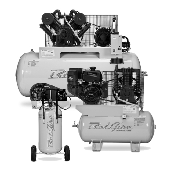
- Page 1 Air Compressor Manual For questions concerning this air compressor, please call 866-869-3114 Rev: 0715 Part# 1312207701...
-
Page 2: Table Of Contents
TABLE OF CONTENTS PAGE Safety Guidelines - Definitions Before Using the Air Compressor When Installing or Moving the Compressor Before Each Use Follow Safety Precautions for Electrical Connection Plan Ahead to Protect Your Eyes, Hands, Face & Ears When Operating Spraying Precautions Perform These Maintenance Operations Typical Compressor Installation... -
Page 3: Safety Guidelines - Definitions
SAFETY GUIDELINES - DEFINITIONS Safety is a combination of common sense, staying alert and knowing how your compressor works. Read this manual to understand this compressor. DANGER means if safety information is not followed someone will be seriously injured or killed WARNING means if safety information is not followed someone could be seriously injured or killed CAUTION... -
Page 4: When Installing Or Moving The Compressor
When installing or moving the compressor WARNING 6. A minimum clearance of 18 inches between the compressor and a wall is required This compressor is extremely top heavy. The because objects could obstruct airflow. compressor must be bolted to the floor with vibration pads before operating to prevent 7. -
Page 5: When Operating
Follow the safety precautions for electrical connections 1. Follow all local electrical and safety codes, 3. Protect wires from contact with sharp objects. as well as the National Electric Code (NEC) and the Occupational Safety and Health Act (OSHA). CAUTION 2. -
Page 6: Spraying Precautions
Spraying precautions WARNING 1. Do Not spray in the vicinity of open flames or other places where a spark can cause Never point a spray gun at yourself or any ignition. Do Not smoke when spraying other person or animal. Accidental discharge paint, insecticides, or other flammable may result in serious injury. -
Page 7: Typical Compressor Installation
TYPICAL COMPRESSOR INSTALLATION WIRING To Air System Flex Regulator Hose See Illustration 1a Dryer Vibration Pads GLOSSARY OF TERMS Air Filter Pressure Switch Porous element contained within a metal or Device which automatically controls the on/off plastic housing attached to the compressor cycling of the compressor. - Page 8 WIRING WIRING WARNING ALL ELECTRICAL WIRING SHOULD BE DONE DO NOT MAKE CONNECTIONS BY A QUALIFIED ELECTRICIAN AT THE PRESSURE SWITCH Single Phase (Units with Magnetic Starters) General Information Adequate wiring and motor protection Incoming power should should be provided for all stationary be connected to L1 and compressors.
- Page 9 WIRING WIRING Single and Three Phase With Mag Starter Page 7...
- Page 10 WIRING WIRING Single and Three Phase Duplex Page 8...
- Page 11 WIRING WIRING Single and Three Phase Page 9...
-
Page 12: Starting The Compressor
STARTING THE COMPRESSOR STARTING THE COMPRESSOR Operate the compressor for a few minutes Prior to actually running the compressor, unloaded (air system open) then allow the check the following items: compressor to pump up. Make sure the electrical pressure switch properly switches Crankcase oil - Make sure the sight glass off the compressor according to the setting shows ½... - Page 13 (Gas Drive Models) PLEASE REFER TO YOUR ENGINE OPERATION MANUAL FOR PROPER STARTING INSTRUCTIONS. GASOLINE DRIVEN COMPRESSORS ARE EQUIPPED WITH A COLD START VALVE FOR LOADLESS STARTS. NOTE: IN SOME INSTANCES, IT STILL MAY BE NECESSARY LIFT THE TOGGLE ON THE UNLOADER/PILOT VALVE TO RELIEVE THE HEAD PRESSURE.
-
Page 14: Qp Compressor
QP Compressors You have purchased a state of the art BelAire QP compressor. The QP comes equipped with sound attenuating enclosure. For maintenance, the canopy and side foam pieces will need to be removed. To remove the canopy, simply remove the 6 fasteners and lift the canopy straight up and off. - Page 15 TROUBLESHOOTING GUIDE Low discharge pressure 1. Reduce air demand or use a compressor 1. Compressor too small for application with more air capacity. 2. Air leaks 2. Listen for air leaks. Apply a soap solution to all fittings and connections. Bubbles will form at points of leakage.
- Page 16 TROUBLESHOOTING GUIDE (Continued) Pressure switch un- 1. Malfunctioning check valve 1. Replace check valve if unloader bleeds loader constantly constantly. leaking air Do not remove check valve DANGER with air pressure in tank Pressure switch not 1. Malfunctioning pressure 1. Replace pressure switch if it does not release unloading switch air pressure briefly when unit shuts off.
- Page 17 WIRING Pump Specifications Pump Model Pump P/N Cyl. No. Stages PAT24 4116091136 PAT38 4116091337 4116090019 T29S 4116090112 B5900 4116090137 1312202800 1312202700 Cyl. Diam. In. (mm) Pump Displacement @ max RPM Stroke in. Oil Cap. Max rpm Model 1st Stg 2nd Stg (mm) Qt.
- Page 18 WARNING Oil and moisture residue must be drained from the air receiver daily or after each use. Accumulations of oil residue in the receiver can be ignited by embers of carbon created by the heat of compression causing an explosion, damage to property and injury to personnel WARNING Do not open a manual tank drain valve on any air tank containing more than 30 PSIG of air pressure!
- Page 19 Part Callouts Electric Discharge Line Compressor Drive Belt Inlet Filter Motor Pressure Switch Check Valve Pressure Gauge Magnetic Starter Tank Ball Valve Water/Tank Drain Gas Drive Inlet Filter Drive Belt Compressor Engine Belt Guard Idle Control Pilot/Unloader Valve Pressure Gauge Ball Valve Tank Water/Tank Drain...
- Page 20 Single Stage *Note: Verify Model and Part Number of Machine Before Ordering Change has been made to Compressor Pumps (March-April 2014) 5020P* 5026VP* 2061V* 6061V* 4116091336 4116091336 4116091337 4116091337 Compressor 1312100388 1312100388 1312100388 1312100390 Motor 1312100473 1312100475 1312100460 1312100460 Tank 1312100170 1312100170 1312100170...
-
Page 21: Two Stage
Two Stage Electric 216V 218V 318VN 318V 318H 338V/4 338H/4 318VE 318HE 338VE/4 Pump 4116090112 4116090112 4116090019 4116090019 4116090019 4116090019 4116090019 4116090019 4116090019 4116090019 Motor 1312101146 1312100389 1312100389 1312100399 1312100399 1312101602 1312101602 1312100399 1312100399 1312101602 Tank 1312100460 1312101018 1312101018 1312101018 1312100485 1312101018 1312100485... -
Page 22: Gas Drive And Duplex
Gas Drive and Duplex Gas Drive 59G3HR 59G3HB 3G3HH 3G3HK 3G3HKL 3G3HHL Compressor 4116090137 4116090137 4116090019 4116090019 4116090019 4116090019 Engine 1312100232 1312100730 1312100223 1312100998 1312100998 1312100224 Tank 1312100479 1312100479 1312100479 1312100479 1312100479 1312100479 Unloader Valve 1312100497 1312100497 1312100497 1312100497 1312100497 1312100497 Safety Valve 9710533300... - Page 23 QP318VE QP338VE QP318VLE QP338VLE Compressor 4116090019 4116090019 4116090019 4116090019 Motor 1312100399 1312100602 1312100400 1312101601 Tank 1312101018 1312101018 1312101018 1312101018 Check Valve 1312100171 1312100171 1312100171 1312100171 Press. Switch 1312100570 1312100570 1312100570 1312100570 Safety Valve 9710533300 9710533300 9710533300 9710533300 Press. Gauge 1312100845 1312100845 1312100845 1312100845...
- Page 24 1312100014 1312100014 1312100014 1312100014 LOS - Housing 1312100013 1312100013 1312100013 1312100013 1312100013 1312100013 Duplex (Iron Series) 4112D 4312D 4312D4 4112DL 4312DL 4312DL4 6312D 6312D4 6320D 6320D4 1312202800 1312202800 Compressor 1312202800 1312202800 1312202800 1312202800 1312202700 1312202700 1312202700 1312202700 Motor 1312100399 1312101602...
- Page 25 Compressor Pump 4116091336 (PAT24) and 4116091337 (PAT38) Page 23...
- Page 26 Compressor Pump 4116091336 (PAT24) and 4116091337 (PAT38) Air Filter Kit 2236111635 Valve Assembly Kit 2236112518 Gasket Kit 2901325045 Bearing and Ring Kit 2901325046 Head Kit 2901325044 Discharge Elbow Kit 2901325047 Cylinder Kit 2236112434(PAT24) 2236112435(PAT38) Oil Level Kit 6229021000 Conrod Kit 2236111619(PAT24) 2236111620(PAT38) Flywheel Kit...
-
Page 27: T29S
Ill. No. Part Number Description 2901324960 Head Kit 2901324961 Intercooler Kit 8973035118 Gasket Kit 6229017300 Overhaul Kit 2901324962 Aftercooler Kit 6229017600 Flywheel Kit 2901324950 Oil Level Kit 2901324963 65 psi Safety Valve 1312100376 Filter Assembly FE004 Filter Element 2236102992 Oil Sight Glass 6211848600 Flywheel Bolt 6214242800... -
Page 28: B5900
Ill. No. Part Number Description 2901324964 Head Kit 2901324965 Intercooler Kit 8973037264 Gasket Kit 6229026900 Overhaul Kit 2901324966 Aftercooler Kit 6229020100 Flywheel Kit 2901324951 Oil Level Kit 2901324963 65 psi Safety Valve 2901324974 217 psi Safety Valve 6211471600 Filter Assembly 8973035122 Filter Element 6214341200... -
Page 29: T39
Ill. No. Part Number Description 2901324971 Head Kit 2901324972 Intercooler Kit 1310711137 Gasket Kit 1310711168 Overhaul Kit 2901324973 Aftercooler Kit 6229018800 Flywheel Kit 2901324954 Oil Level Kit 1312100456 225 psi Safety Valve 1312100374* Filter Assembly FE001* Filter Element 2236102992 Oil Sight Glass 6211848500 Flywheel Bolt 6214242700... - Page 30 (1312202800) Page 28...
- Page 31 (1312202800) Item Description Part # Capscrew-Hex M10x30 0147136303 Crankcase 1312100876 Copper Gasket 10 1312100923 Crank Shaft 1312100932 Aftercooler 1312100875 Fly Wheel 1312100884 Gasket Valve Cover 1312100919 Cylinder 1312100880 Elbow - Street 1312100865 Valve Assy HP Inlet 1312100891 Head 1312100878 Oil Sight Glass 1312100903 Safety Valve 250 psi 1312100862...
- Page 32 (1312202700) Page 30...
- Page 33 (1312202700) Item Description Part # Aftercooler 1312100874 Crankcase 1312100877 Gasket Valve Cover 1312100919 Crank Shaft 1312100931 Valve Assy HP Inlet 1312100891 Fly Wheel 1312100883 Safety Valve 250 psi 1312100862 Cylinder 1312100880 Gasket Aftercooler 1312100918 Head (Left) 1312100878 Elbow Aftercooler 1312100872 Head (Right) 1312100879 Gasket - Cylinder Head...
- Page 36 Warranty Statement The Company warrants that the Equipment manufactured by it and delivered hereunder shall be free from defects in material and workmanship for a period of twelve (12) months from the date of initial start-up, or eighteen (18) months from the date of shipment from the manufacturer, whichever occurs first.
Need help?
Do you have a question about the 3G3HHL and is the answer not in the manual?
Questions and answers