Table of Contents
Advertisement
Quick Links
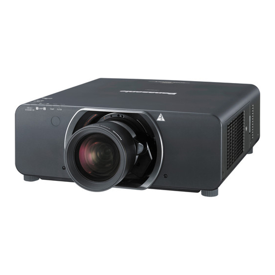
The projection lens is sold separately.
3-chip DLP Based Projector
PT-DZ13KU
Model No.
PT-DZ13KE
PT-DS12KU
PT-DS12KE
PT-DW11KU
PT-DW11KE
PT-DZ10KU
PT-DZ10KE
Replacement lamp unit
■
ET-LAD310A (1 pc)
ET-LAD310AW (2 pcs)
Replacement filter unit
■
ET-EMF320
Replacement lamp unit
■
(for portrait mode)
ET‑LAD320P (1 pc)
ET‑LAD320PW (2 pcs)
© Panasonic Corporation 2013. Unauthorized
copying and distribution is a violation of law.
ORDER NO. VED1304464CE
D10
Rev._2 2013-05
Advertisement
Chapters
Table of Contents

Related Manuals for Panasonic PT-DW11KU


Summarization of Contents
Important Safety Notice
General Safety Precautions
Covers electrical safety, handling, and general warnings.
UV Radiation and Lithium Battery Hazards
Specific warnings about UV radiation and lithium battery risks.
Lead-Free Solder Servicing Guidelines
Precautions for using lead-free solder in repairs.
FCC Compliance Statement
Information regarding the device's compliance with FCC regulations.
Safety Precautions
General Guidelines
Basic safety rules for service technicians.
Leakage Current Check
Procedure to measure leakage current to prevent electric shock.
UV and UHM Lamp Precautions
Safety measures for handling the high-pressure lamp and UV radiation.
Specifications
Projector Specifications Overview
Lists technical details of the projector, including power, consumption, size, and optical parameters.
Applicable Scanning Frequency
Details compatible video signal scanning frequencies for the projector.
Terminal Specifications
Describes projector input/output terminals and signal compatibility.
SECTION 1 Service Information
Part Identification Overview
Identifies and describes the projector's physical components and their locations.
Menu Navigation Overview
Explains how to navigate the projector's on-screen menus and settings.
Service Mode Access and Functions
Details how to enter and utilize the projector's service mode for advanced operations.
External Control Interfaces
Describes methods for controlling the projector externally via serial, LAN, and remote interfaces.
Service Operation Notes and Precautions
Provides critical considerations, precautions, and procedures for performing service.
Troubleshooting Common Issues
Offers guidance for diagnosing and resolving projector malfunctions and errors.
Service Mode Access and Functions
Setting to Service Mode
Step-by-step instructions on how to enter the projector's service mode using the remote or panel.
Resetting to User Mode
Procedure to return the projector from service mode to user mode.
Service Mode Additional Functions
Details functions like Self Check, Error OSD, Convergence, and Model settings.
External Controls and Connectivity
Serial Terminal Communication
Details serial control, including connection, pin assignments, and communication conditions.
LAN Terminal Communication
Procedures for controlling the projector via LAN, including web control and protected/unprotected modes.
Control Commands List Reference
Refers to a separate document for a comprehensive list of control commands.
Service Notes and Precautions
Lamp Replacement Guidance
Provides essential information and precautions regarding lamp replacement.
Air Filter Unit Maintenance
Instructions on cleaning and replacing the projector's air filter unit.
Smoke Cut Filter Installation and Use
Guidelines for using and installing the optional smoke cut filter.
Service Operations and Repair Policies
Service Support Methods
Outlines the basic service policy and applied parts for repairs.
Repair Safety and Procedures
Details safety measures and checks required during and after projector repair.
Interlock Detection Mechanism
Explains the interlock system that prevents power-on if certain connectors are dislodged.
Consumable Parts Replacement Guidance
Lamp Unit Replacement Procedure
Detailed instructions and cautions for safely replacing the projector lamp unit.
Troubleshooting Guide
Shutdown System Error Indicators
Details projector shutdown indicators and probable causes for system faults.
System Log Data Acquisition Method
Instructions for collecting system log data using service software and connection preparations.
System Log Error Code Reference
Lists and explains various error codes found in the system log data for diagnosis.
Power-On Troubleshooting Flowcharts
Diagnostic steps for power-on issues indicated by power indicator status.
Lamp Operation Troubleshooting
Diagnoses problems related to the projector lamp indicators and power supply.
Image Display Troubleshooting
Guides on diagnosing and resolving problems where no image or abnormal image appears.
Video Input Signal Troubleshooting
Details checks for video, Y/C, and RGB1 input signals for image display issues.
RGB2 Input Signal Troubleshooting
Specific diagnostic steps for troubleshooting RGB2 input signal problems.
DVI-D and HDMI Input Signal Troubleshooting
Guides on diagnosing issues related to DVI-D and HDMI video inputs.
SDI Input Signal Troubleshooting
Explains diagnostic steps for SDI1 and SDI2 input signal problems.
Signal Processing and APC Board Checks
Covers checks for PinP mode and general A-P.C. Board operation related to signal processing.
Control System Troubleshooting
Diagnoses problems with main CPU operation and remote control responsiveness.
Communication Interface Troubleshooting
Addresses issues with serial, remote, and side panel control interfaces.
SECTION 2 Disassembly Procedures
Parts Location Diagrams
Visual diagrams showing the location of electronic parts and fans on the circuit boards.
Disassembly Instructions Flowchart
Outlines the sequence of steps for disassembling the projector.
Wiring Diagrams
Illustrates the internal wiring connections for various projector components and circuit boards.
Wiring Diagrams
Bottom Case Wiring Details
Shows wiring connections within the projector's bottom case.
Ballast Block Wiring Diagram
Illustrates the wiring connections for the ballast block.
SECTION 3 Adjustments
Adjustment Items and Procedures Overview
Lists components requiring adjustment after replacement and their procedures.
Software Update Procedures
Guides on updating projector firmware via LAN or serial connections.
SECTION 4 Schematic Diagram
Block Diagrams Overview
High-level diagrams illustrating power supply, control, and signal processing systems.
Interconnection Block Diagram
Shows how different circuit boards connect and interact within the projector.
Schematic Diagrams of Major Boards
Detailed circuit diagrams for specific P.C. boards like A-P.C.Board and G-P.C.Board.
Circuit Board Component Layouts
Visual representation of component placement on the A-P.C.Board and G-P.C.Board.
SECTION 5 Exploded Views & Parts List
Exploded View Diagrams
Visual diagrams showing how projector parts are assembled, detailing component locations.
Replacement Parts List
Comprehensive list of all replaceable parts with their part numbers and descriptions.
Need help?
Do you have a question about the PT-DW11KU and is the answer not in the manual?
Questions and answers