
Related Manuals for ScioSense PCap04 LITE V1.0 BGRP


Summary of Contents for ScioSense PCap04 LITE V1.0 BGRP
- Page 1 PCap04-EVA-KIT V2.0 Development Kit User Guide PCAP04-EVA-KIT 2.0 Revision: 2 Release Date: 2023-05-16 Document Status: Production...
-
Page 2: Table Of Contents
Scaling Results ..................37 Scaling PDM Output .................. 39 Schematics, Layers & BOM ................40 RoHS Compliance & ScioSense Green Statement ............ 42 Copyrights & Disclaimer .................. 42 Revision information ..................43 PCAP04-EVA-KIT User Guide SC-001587-UG 2 / 2023-05-16 / Production... -
Page 3: Introduction
220300005 PCap04 evaluation board Quick Start Guide In this section, we described how to set up quickly the PCap04-EVA-KIT V2.0 and establish basic operation and make measurements. Installing the Software It is crucial to install the software before connecting the evaluation kit to your computer. A default driver loading of your OS may interfere with correct installation. -
Page 4: Installing The Hardware
I2C communication. They are marked accordingly. Quick Start for Initial Measurements In the START menu search for PCap04 or look under program folder ScioSense for the PCap04 software and start it. The software pops up with the following window: Figure 2: Start page On the right site a little icon indicates whether a device is connected and whether SPI or I2C is used. - Page 5 CONTENTS PAGE Figure 3: Verify The PCap04 plug-in board is pre-assembled with ceramic capacitors to emulate capacitive sensors. These capacitors, each 10 pF in value, are connected to the 6 ports PC0 to PC5. To begin measurements using these preinstalled components, it is necessary to make the following adjustments on the “CDC Frontend”...
- Page 6 CONTENTS PAGE To begin measurements, on the right side of the window, click the following buttons in the order listed: 1) “Power On Reset” 2) “Write Complete” 3) “Start Measurement” Measurements should now be running and your screen should resemble the following: Figure 5: CDC Frontend page with running measurement The C1 and C2 values should be continually updating but remain within a reasonably small standard deviation as shown.
-
Page 7: Hardware Description
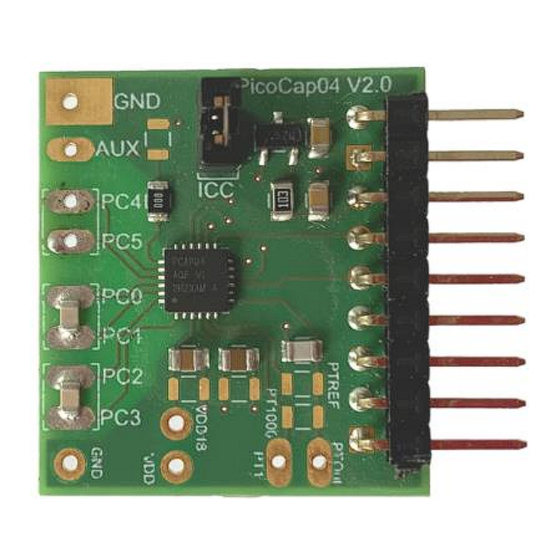
CONTENTS PAGE Hardware Description PCap04 Lite Board 3.1.1 Capacitance Measurement For the purpose of evaluating the capacitance measurement using PCap04, the board is pre- assembled with ceramic capacitors to emulate capacitive sensors. These capacitors, each 10 pF in value, are connected to the 6 ports PC0 to PC5. They are connected as single sensors in floating mode, i.e. - Page 8 CONTENTS PAGE Figure 7: Temperature sensor connection pads Port PT1 for second external temperature sensor (not supported by the standard firmware) Port PT0 for external temperature sensor Port PT2 for external reference resistor 10 nF COG However, there is a possibility to connect the reference resistor and the thermistor externally to the chip, too.
-
Page 9: Software Description
CONTENTS PAGE 1 Software Description 1.1 Initialization Configuration files, Firmware, Settings and Calibration Data are subsumed in a project (.prj) file. When opening a project file then automatically the configuration and firmware data will be transferred to the chip and the chip is initialized. Step 1: The first to do after starting the evaluation software is to read the device version from Chip by pressing the button or to select the supported PICOCAP device on the setup page. - Page 10 CONTENTS PAGE 1.2.1.1 Setup Page Figure 8 Setup page Options on ‘Setup’ page: Standard Opens the <Selected Device>_standard.prj project file with configuration and standard firmware. Humidity Opens the <Selected Device>_humidity.prj project file with configuration and linearization firmware. Pressure Opens the <Selected Device>_pressure.prj project file with configuration and linearization firmware.
- Page 11 CONTENTS PAGE The tab has 12 columns of information, defining labels, data format, resolution specification (white background) and results (grey background). The information in the white fields increase convenience of reading and is stored in the project files (*.prj). All number may get a character to indicate the well-known prefixes for denoting the factor in thousands (‘p’, ‘f’, ‘a’, ‘k’...
- Page 12 CONTENTS PAGE 1.2.1.2 CDC Frontend Page Figure 9 CDC Frontend page PCAP04-EVA-KIT User Guide SC-001587-UG-2 / 2023-05-16 / Production...
- Page 13 CONTENTS PAGE Options on ‘CDC Frontend’ page: Capacitance Measurement Grounded | Single – Single capacitive sensor connected between a port and ground. Scheme Grounded | Differential – Differential capacitive sensor connected between 2 ports with the middle tap of the sensor connected to ground. Floating | Single –...
- Page 14 CONTENTS PAGE 1.2.1.3 CDC Page Figure 10 CDC page Options on ‘CDC’ page: Cycle Control Precharge Time Time to charge via resistor for current limitation, can be set in multiples of the cycle clock Fullcharge Time Time for final charge without current limitation, can be set in multiples of the cycle clock Discharge Time Time to discharge the capacitor, can be set in multiples of the cycle clock C_FAKE...
- Page 15 CONTENTS PAGE Conversion Duration Displays the entire conversion duration per cycles for averaging and fake measurements. C_TRIG_SEL Selects the source that triggers the start of a capacitance measurement Continuous – Continuous measurement, self-triggering. Recommended when no temperature measurement is made in parallel. Read Triggered –...
- Page 16 CONTENTS PAGE 1.2.1.4 RDC Page Figure 11 RDC page Options on ‘RDC’ page: Temp.Sensor0 To select a thermistor connected to port PT0/REF for temperature measurement. This could be e.g. an external PT1000. Temp.Sensor1 To select a thermistor connected to port PT1 for temperature measurement. Temp.Sensor2 To select either the internal aluminium (ALU) thermistor for temperature measurement.
- Page 17 CONTENTS PAGE R_FAKE Set number of fake measurements per temperature measurement cycle. Conversion Duration Displays the entire conversion duration per cycles for averaging and fake measurements. Conversion Control Temp. Trigger Select Selects the source that triggers the start of a temperature measurement: Off: Default setting when no temperature measurement is wanted.
- Page 18 CONTENTS PAGE 3.1.2.1 PDM / PWM Page Figure 12 PDM/PWM page Options on ‘PDM / PWM’ page: Clock Select Selects the clock frequency to be used for the PWM/PDM generation. Resolution Resolution of the output in bits. This resolution also determines the pulsed output range. Pulse Interface Select Select the pulse interface –...
- Page 19 CONTENTS PAGE 3.1.2.2 DSP/GPIO Page Figure 13 DSP/GPIO page PCAP04-EVA-KIT User Guide SC-001587-UG-2 / 2023-05-16 / Production...
- Page 20 CONTENTS PAGE Options on ‘DSP/GPIO’ page: DSP_SPEED Select the DSP Speed. Choose between Fastest, Fast, Slow and Slowest. DSP_FF_IN Pin mask for latching flip-flop activation (PG0 to PG3) DSP_MOFLO_EN Activates anti-bouncing filter in PG0 and PG1 lines DSP_STARTONPIN Not supported by standard firmware The DSP can be started externally by a signal on a pin;...
- Page 21 CONTENTS PAGE 3.1.2.3 Misc. Page Figure 14 Miscellaneous page Options on ‘Miscellaneous’ page: LF Clock OLF_CTUNE Coarse-tune the low frequency clock. (10kHz, 50kHz, 100kHz, 200kHz) OLF_FTUNE Fine-tune the low frequency clock. (0..15) HF Clock OX_RUN Controls the permanency or the latency of the OX generator. Latency means an oscillator settling time before a measurement starts.
-
Page 22: Front Panel Menus
Capacitive attenuation of Guarding OP. C_G_OP_VU OP Gain (from Sense Port to Guard). 3.1.2.4 Expert Page Please modify the settings on the Expert page only in consultation with ScioSense Support team. 3.1.3 Front Panel Menus 3.1.3.1 File Menu Figure 15 File Menu Open Project Open project file *.prj that subsumed the firmware and configuration filenames and the... - Page 23 CONTENTS PAGE Close Close the evaluation software 3.1.3.2 Memory Menu Figure 16 Memory Menu Firmware Opens the window to download the firmware. (section 4.2.3.1) Calibration Opens the Calibration window (section 4.2.3.2) Read Config from Reads back the configuration information from the NVRAM and overwrites those of the NVRAM GUI.
- Page 24 CONTENTS PAGE 3.1.3.4 Interface Menu Figure 18 Interface Menu Select between SPI and I2C interface Opens the USB Communications window with PicoProg V3.0 Settings and the possibility to send opcodes 3.1.3.5 Help Menu Figure 19 Help Menu Help Contents Opens the help window Check Errors Opens the error message window if there is an inconsistency after plausibility check.
-
Page 25: Special Windows
CONTENTS PAGE 3.1.4 Special Windows 3.1.4.1 Firmware Window In the ‘Firmware’ Window the write data can be edited. If the NVRAM is read (‘Read’ button), the content is automatically compared with the ‘Write Data’ window content. If contents are equal this will be indicated by a green illuminated LED. Figure 20 Firmware Window Open File Select and open a firmware file (.hex) or import firmware from a project file. - Page 26 CONTENTS PAGE Firmware Version In the firmware, a specific address is reserved to save 3 byte information about the application and the version of the software. The coding is specified in the header file of the supported PICOCAP device, for example: pcap_standard.h. The header file is found in the library directory of the assembler.
- Page 27 CONTENTS PAGE 3.1.4.3 Misc. Calibration Window This window shows miscellaneous calibration bits at address d’956-d’959 (4 byte). The meaning of the content strongly depends on the firmware. Figure 22 Misc. Calibration Window Write Writes the data into the chip’s NVRAM. Read Pressing this button, the bits are read from the NVRAM and shown in the tab.
- Page 28 CONTENTS PAGE 3.1.4.4 Complete Memory Figure 23 Complete Memory Window Write Writes the complete NVRAM. Store The complete data transfer from Memory (volatile) to FLASH (non-volatile) is performed by a STORE Erase During this ERASE procedure, first the complete NVRAM will erased (set to zero) and afterwards the MEM_LOCK bits will be cleared.
- Page 29 CONTENTS PAGE 3.1.4.5 Graph Window Figure 24 Graph Window The data to be displayed are selected in the field at the bottom right. The labels in the buttons are the same as in the diagnostics window. To display data press the corresponding button so that it gets green.
- Page 30 CONTENTS PAGE Figure 25 Write Registers and Results PCAP04-EVA-KIT User Guide SC-001587-UG-2 / 2023-05-16 / Production...
-
Page 31: Linearize
CONTENTS PAGE 3.1.5 Linearize 3.1.5.1 Sensor Characterization The first step is the characterization of the sensor. Therefore, it is necessary to collect data at several measurement points and at several temperatures. As mentioned earlier, the data collection should be made of minimum 12 measurements, taken at least at 3 different temperatures. - Page 32 CONTENTS PAGE 3.1.5.2 Temperature Sensor Characterization Together with the calibration of the capacitance sensor it is mandatory to calibrate the temperature, too. Whether the internal aluminum sensor is used or an external platinum sensor or any other sensor: they need to be calibrated to get the correct temperature information which is then used as input for the polynomial correction of the capacitance measurement.
- Page 33 CONTENTS PAGE 3.1.5.3 One/Two Point Calibration Once a batch is characterized with respect to the capacitive sensor and the resistive temperature sensor it might be sufficient to perform two-point or even one-point calibration for the rest of the sensors in the batch. The tab “One/Two Point Calibration”...
- Page 34 CONTENTS PAGE 3.1.5.4 Pulse Figure 29 Pulse PCAP04-EVA-KIT User Guide SC-001587-UG-2 / 2023-05-16 / Production...
- Page 35 CONTENTS PAGE 3.1.5.5 Expert As indicated by the name this tab is for experts only. There you set the fixed point position of the result Z. It further displays the numbers of division steps respectively shift operation to achieve the maximum resolution over all calculations.
- Page 36 CONTENTS PAGE 3.1.5.6 Assembler Figure 31 Assembler This is a comfortable editor with syntax highlighting, search and replace, copy and paste functions. Under menu item “Assembler” the user finds the compile and download options. Whether the call of these functions was successful or not is indicated by the messages at the bottom of the assembler window.
-
Page 37: Scaling Results
CONTENTS PAGE Scaling Results PCap04 in general calculates capacitance ratios. The measured ratios include of course all effects from parasitic capacitances. Nonetheless, in many cases users might be interested in an intuitive understanding the displayed values without making a full calibration run. The following shows by example how to set Factor and Offset to give a suitable display. - Page 38 CONTENTS PAGE Figure 34 Ground single, internal compensation d) Floating single, internal compensation Again, the chip sees only the port parasitic capacitance. But due to the different port pattern the correction factors are slightly higher. Figure 35 Floating single, internal compensation Using floating in combination with an internal reference there is a deviation as we have internally only a single grounded capacitor.
-
Page 39: Scaling Pdm Output
CONTENTS PAGE Scaling PDM Output Here we describe how to scale the PDM output when working with the standard firmware. Open the Memory window and select tab calibration: Figure 37 Scaling PDM Output Set fpp to 27 and s/u to S for signed. Enter the capacitance ratios at minimum and maximum sensor signal. -
Page 40: Schematics, Layers & Bom
CONTENTS PAGE Schematics, Layers & BOM Figure 38: PCap04 LITE BGRP schematics PCAP04-EVA-KIT User Guide SC-001587-UG-2 / 2023-05-16 / Production... - Page 41 CONTENTS PAGE Figure 39: PCap04 LITE layout 2:1t Table 2: Bill of materials for PCap04 LITE Quantity Designator Value Comment Footprint J3, J4, J5 CHIP-CAPACITOR 0805 10n/C0G CHIP-CAPACITOR 0805 100n CHIP-CAPACITOR 0805 CHIP-CAPACITOR 0805 CHIP-CAPACITOR 0805 CHIP-CAPACITOR 0805 CHIP-RESISTOR 0805 CHIP-RESISTOR 0805 PCap04 QFN24 3,0V...
-
Page 42: Rohs Compliance & Sciosense Green Statement
Important Information: The information provided in this statement represents Sciosense B.V. knowledge and belief as of the date that it is provided. Sciosense B.V. bases its knowledge and belief on information provided by third parties, and makes no representation or warranty as to the accuracy of such information. -
Page 43: Revision Information
CONTENTS PAGE Revision information Table 3: Revision history Revision Date Comment Page 1.0.2 2017 Latest version with old PICOPROG May 2023 Release of second version for the kit which comes with PicoProg Lite Note(s) and/or Footnote(s): 1. Page and figure numbers for the previous version may differ from page and figure numbers in the current revision. - Page 44 Sciosense B.V. Address: Sciosense B.V. High Tech Campus 10 5656 AE Eindhoven The Netherlands Contact: www.sciosense.com info@sciosense.com...
Need help?
Do you have a question about the PCap04 LITE V1.0 BGRP and is the answer not in the manual?
Questions and answers