
Related Manuals for Epiroc CC 2300


Summary of Contents for Epiroc CC 2300
- Page 1 1600, 2300, 3100, 3700 Safety and operating instructions Hydraulic demolition cutter © Construction Tools GmbH | 33905197 01 | 2019-03-21 Original Instructions...
-
Page 3: Table Of Contents
Contents Table of Contents 1 Introduction .......................... 8 About these Safety and Operating Instructions.................... 8 2 Safety instructions........................ 9 Signal words................................ 9 Qualification .............................. 10 Intended use .............................. 10 Use other than intended ........................... 10 Protective equipment............................ 11 Carrier, precautions ............................ 11 Transport, precautions ............................. 11 Hydraulic installation, precautions ......................... 12 Media/consumables, precautions........................ 12 2.10 Explosion and fire, precautions........................ 13 2.11 Electrical shock, precautions .......................... 13... - Page 4 Contents Attaching the hydraulic attachment to the carrier .................. 23 5.4.1 Mechanical mounting aspects ......................... 23 5.4.2 Making the hydraulic connections ........................ 23 Removing the hydraulic attachment from the carrier.................. 25 5.5.1 Dismantling the hydraulic connections ...................... 25 5.5.2 Mechanical disassembly.......................... 26 Removing the adapter plate .......................... 26 Valve block ................................ 26 Cutter jaws................................. 27 5.8.1...
- Page 5 Contents Checking hydraulic demolition cutter for wear.................... 48 Checking hydraulic lines.......................... 48 Checking bolted connections .......................... 48 Checking the adapter plate bolts for wear...................... 49 7.10 Checking and cleaning the hydraulic oil filter of the carrier................. 49 7.11 Turning or changing the cutter blades ...................... 49 7.11.1 Removing the cutter blades..........................
- Page 6 Contents 11.3 Hydraulic oil .............................. 69 11.4 Cutter grease and grease cartridges....................... 69 12 Technical specifications...................... 70 13 EC Declaration of Conformity (EC Directive 2006/42/EC) ............ 74 13.1 CC 3100 P................................ 75 © Construction Tools GmbH | 33905197 01 | 2019-03-21 Original Instructions...
- Page 7 Contents © Construction Tools GmbH | 33905197 01 | 2019-03-21 Original Instructions...
-
Page 8: Introduction
1.1 About these Safety and 1 Introduction Operating Instructions Epiroc is a leading productivity partner for the mining, in- frastructure and natural resources industries. With cut- The aim of these Instructions is to familiarise you with ting-edge technology, Epiroc develops and produces in-... -
Page 9: Safety Instructions
Safety and operating instructions 2.1 Signal words 2 Safety instructions The signal words Danger, Warning, Caution, and Notice This is the safety alert symbol. It is used to alert are used as follows in these Safety and operating in- you to potential personal injury hazards. Obey structions: all safety messages that follow this symbol to avoid possible injury or death. -
Page 10: Qualification
Safety and operating instructions 2.2 Qualification 2.3 Intended use Transporting the hydraulic attachment is only permitted Only attach the hydraulic demolition cutter to a hydraulic if carried out by people who: carrier of a suitable load-bearing capacity. Read the car- rier manufacturer's Safety and Operating Instructions be- •... -
Page 11: Protective Equipment
Safety and operating instructions • to push debrisThis destroys the hydraulic demolition 2.7 Transport, precautions cutter. • to move the carrier supported by the hydraulic de- WARNING Risk of death due to suspended loads molition cutterThis severely damages the hydraulic When lifting loads these can swing out and fall. -
Page 12: Hydraulic Installation, Precautions
Safety and operating instructions 2.8 Hydraulic installation, 2.9 Media/consumables, precautions precautions WARNING Hydraulic pressure too high WARNING Hot hydraulic oil under high pressure If the hydraulic pressure is too high, the parts of the hy- Hydraulic oil will squirt out under high pressure if there is draulic attachment will be exposed to excessively high a leakage. -
Page 13: Explosion And Fire, Precautions
Safety and operating instructions 2.10 Explosion and fire, 2.11 Electrical shock, precautions precautions DANGER Electrical shock Any contact of the hydraulic attachment with electric cir- DANGER Explosion and fire cuits or other sources of electricity will lead to an electric Explosions cause serious injury or death. -
Page 14: Emissions, Precautions
Never carry out any changes to the hydraulic attach- ment or the adapter plate. u Only use original parts or accessories approved by Epiroc. u Modifications that entail new hazards may require a new procedure for assessing conformity. © Construction Tools GmbH | 33905197 01 | 2019-03-21... -
Page 15: Overview
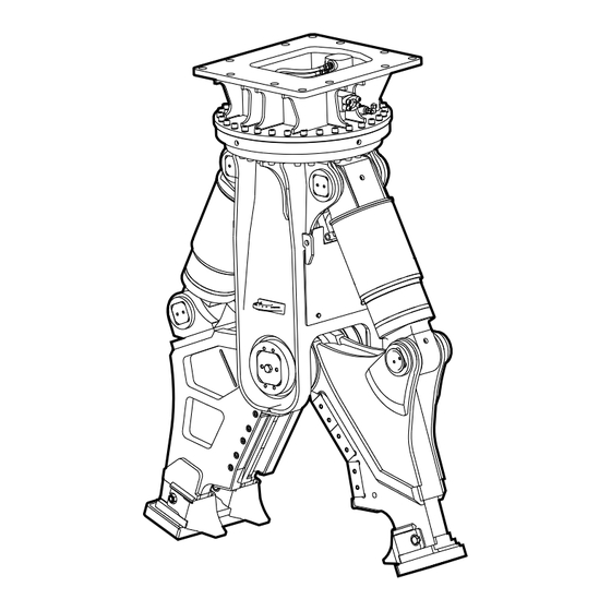
Safety and operating instructions 3 Overview A. Cutter blades B. Cutter jaw (double) C. Four-point bearing 3.1 Equipment description D. Connection function »Turn« E. Connection »A« function »Open« The illustration gives an overview of the main parts and Adapter plate (not supplied with the hydraulic demo- components of the hydraulic attachment. -
Page 16: Signs / Labels
Safety and operating instructions The CE symbol indicates that the hydraulic attach- 3.3 Signs / labels ment was produced in conformity with the CE. You can find further information about this in the en- WARNING Missing warnings closed EC Declaration of Conformity. The name plate and the labels on the hydraulic attach- The EAC symbol means that the machine is EAC ment contain important information about the hydraulic... -
Page 17: Applications
Check that the delivery is complete. trial demolition (heavily rein- forced concrete) n Check the delivery for visual damage. Cutting profiled steel (general n If any defects are found, consult the Epiroc Customer construction steels) Center / dealer in your area. Subsequent reduction Material separation 3.7 Scope of delivery... -
Page 18: Transport
Only lift and secure the hydraulic attachment with lift- seam. ing gear (ropes, chains, shackles etc.) with the right u Contact the Epiroc Customer Center / Dealer in your load-bearing capacity for the weight to be lifted. area if the lifting eye is worn in any way. -
Page 19: Transport Using A Crane
Safety and operating instructions 4.1 Transport using a crane 4.2 Transport using a forklift truck n Secure the hydraulic attachment with ropes or chains as shown in the following illustration. WARNING Hydraulic attachment tipping over The hydraulic attachment tipping off the fork of the forklift truck or the pallet may cause serious injury. -
Page 20: Transport Using A Truck
Safety and operating instructions 4.3 Transport using a truck WARNING Hydraulic attachment tipping over / slipping The hydraulic attachment slipping or tipping over and falling from the loading area of a lorry may cause serious injury. u Place the hydraulic attachment on a pallet. u Strap the hydraulic attachment to the pallet using suitable strapping (see illustration in chapter Trans- port using a forklift truck). -
Page 21: Installation
Dispose of it in accordance with the applicable envi- Our hydraulic attachments are basically designed for use ronmental regulations. with mineral oils. Consult the Epiroc Customer Center / Dealer in your area before using other hydraulic oils ap- 5.1 Media/consumables proved by the carrier manufacturer. -
Page 22: Manufacturing The Adapter Plate
Type Key size Tightening torque plate side marked "TOP". CC 1600 22 mm (0.89 in.) 1500 Nm (1106 ft lbs) The adapter plate must not strike in any position during CC 2300 22 mm (0.89 in.) 1500 Nm (1106 ft lbs) operation of the hydraulic attachment. -
Page 23: Attaching The Hydraulic Attachment To The Carrier
The adapter plate must not be stopped by the mechani- cut off or hurt parts of your body. cal stops in either position. Consult the Epiroc Customer u Never use your fingers to check bores or fitting sur- Center / Dealer in your area if the adapter plate is faces. - Page 24 Safety and operating instructions NOTICE Damage to hydraulic parts When both input lines have the same operating pres- sures, Polluted hydraulic lines and connections may enable sand, fragments of material and dirt to penetrate the hy- n connect the two hoses at the boom in a torsion-free draulic attachment and damage the hydraulic parts.
-
Page 25: Removing The Hydraulic Attachment From The Carrier
Safety and operating instructions 5.5 Removing the hydraulic WARNING Hydraulic hose flailing about Pressurised hydraulic hoses will flail about if a bolted attachment from the carrier connection comes loose or becomes loosened. A hy- n Place the hydraulic attachment on timber support draulic hose flailing about may cause serious injuries. -
Page 26: Mechanical Disassembly
Safety and operating instructions 5.5.2 Mechanical disassembly 5.6 Removing the adapter plate n You need an assistant to remove the hydraulic at- n Loosen the fastening screws of the adapter plate. tachment. n Lift the adapter plate with a suitable lifting equipment n Agree on hand signals with your assistant, to enable and put it down on timber support blocks. -
Page 27: Cutter Jaws
Safety and operating instructions Removing the cutter jaw pair 5.8 Cutter jaws n Ensure that the hydraulic demolition cutter is me- chanically and hydraulically attached to the carrier. 5.8.1 Selecting the correct jaw variant n Ensure that the cutter jaws are connected by two half The standard available jaw variants are shown. - Page 28 Safety and operating instructions n Place the hydraulic demolition cutter with the broad back of the cutter jaw (double) on the assembly rack so that the pin lies in the semi-shell of the assembly rack. n Retract the hydraulic cylinder. n Disassemble the bolts (F) from the empty assembly rack.
- Page 29 Safety and operating instructions n Remove the hexagon head screw (M) located in the n Disassemble the Allen screws (K) from the cover. middle of the main bearing pin. n Attach the bolt cage (N). n Screw the two Allen screws (L) into the cover. n Unscrew the cover using a rod or pipe.
- Page 30 Safety and operating instructions n Drive the main bearing pin (O) out with a copper mandrel until it stops at the bolt cage (N). n Fix the main bearing pin (O) with the hexagon head screw (M) to the bolt cage (N). The main bearing pin is thus secured against inad- vertantly slipping in.
- Page 31 Safety and operating instructions Fitting the cutter jaw pair An assistant is required to attach the cutter jaw pair. n Agree on hand signals with your assistant, to enable him to help you place the carrier in the proper posi- tion.
- Page 32 Safety and operating instructions n Loosen all Allen screws (I) at the holders (G) of the n Secure the cover by fitting the Allen screws (K). assembly rack. n Disassemble the Allen screws (H,J) from the pin of n Tighten the Allen screws (K) with the tightening the assembly rack.
- Page 33 Safety and operating instructions n Let the hydraulic demolition cutter hang vertically on the carrier, do not place it on the ground. n Extend the hydraulic cylinders. n Secure the carrier such that it cannot move unexpect- edly. n Align the drilled holes for the cylinder pins (D). n Fit the cylinder pins (D).
- Page 34 Safety and operating instructions n Lubricate the hydraulic demolition cutter (see chapter Lubrication). n Store the disassembled cutter jaw pair safely (see chapter Storage). © Construction Tools GmbH | 33905197 01 | 2019-03-21 Original Instructions...
-
Page 35: Operation
Safety and operating instructions 6.1 Preparations before starting 6 Operation WARNING Falling carrier WARNING Hot hydraulic oil squirting out A carrier falling or tipping over due to the surface not be- The hydraulic system is under high pressure. If hydraulic ing level may cause serious injury and material damage. -
Page 36: Switching The Hydraulic Attachment On And Off
Switch the hydraulic attachment off immediately if oil manufacturer and/or the Epiroc Customer Center / leaks from the hydraulic lines or other malfunctions Dealer in your area. -
Page 37: Correct Operation
Safety and operating instructions 6.4.3 Nipping out concrete elements 6.4 Correct operation n Nip concrete elements off at both sides. 6.4.1 Demolishing concrete ceilings or walls n Encompass the concrete ceilings and walls as far as possible with the hydraulic demolition cutter. In high reinforced concrete structures n First break the concrete with the tip of tooth area. -
Page 38: Cutting Profiled Construction Steel, Pipe
Safety and operating instructions 6.4.6 Cutting profiled construction steel, pipe n Position the hydraulic demolition cutter so that the blades encompass the profiled construction steel or pipe. 6.4.7 Cutting wide profiled construction steel n First cut one half of the profiled construction steel. The tip of the cutter jaw penetrates the web plate. -
Page 39: High Ambient Temperature
Safety and operating instructions 6.4.8 High ambient temperature 6.5 Prohibited operation n Only use hydraulic oils of sufficient viscosity. In summer and in tropical climates, the minimum re- 6.5.1 Unsafe base quirement is a hydraulic oil of type HLP 68. WARNING Danger of tipping The carrier can topple over and cause injuries and dam- 6.4.9 Low ambient temperature age. -
Page 40: Cutting Rails
Safety and operating instructions 6.5.3 Cutting rails 6.5.5 Use over the chain WARNING Flying rail fragments WARNING Danger of tipping Rails which break during the cutting process may be The carrier can topple over and cause injuries and dam- flung away and can cause serious injury if people are hit age. -
Page 41: Moving The Carrier
Safety and operating instructions 6.5.7 Moving the carrier 6.5.9 Turning the hydraulic attachment n Never relocate the carrier sideways by placing the n Never turn the hydraulic attachment during breaking/ hydraulic attachment on the ground to lift the carrier. cutting. This would seriously damage the hydraulic attach- This would seriously damage the hydraulic attach- ment. -
Page 42: Pulling
Safety and operating instructions 6.5.11 Pulling 6.5.13 Impacting/chopping n Never pull at girders, supports or walls with the hy- n Do not use the hydraulic attachment to impact or draulic attachment. chop to destroy material. This would damage the hydraulic attachment and the This would seriously damage the hydraulic attach- adapter plate. -
Page 43: Cylinder End Positions
Safety and operating instructions 6.5.15 Cylinder end positions 6.5.16 Use under water n Reposition the carrier to avoid working with the cylin- n Never use the hydraulic attachment under water. der in its end positions. This would seriously damage the hydraulic attach- Avoid operating the hydraulic attachment when the ment and may damage the whole hydraulic installa- carrier stick and bucket cylinder are in one of their... -
Page 44: Maintenance
Safety and operating instructions 7 Maintenance WARNING Unexpected movement Sudden movements of the carrier may cause serious in- The maintenance activities are carried out by the carrier jury. driver. u Secure the carrier such that it cannot move unex- pectedly. WARNING Hot hydraulic oil squirting out u Observe the carrier manufacturer’s instructions. -
Page 45: Maintenance Schedule
Safety and operating instructions 7.1 Maintenance schedule prior to shift Check the hydraulic demolition cutter and adapter plate for cracks. Check hydraulic lines for leaks and damage. Check the pipe clamp receiver on the carrier. Check cutter jaws, cutter blade and tips of tooth for wear; if necessary have cutter jaws refaced, turn or replace cutter blades, replace tips of tooth. -
Page 46: Depressurising The Hydraulic System
Safety and operating instructions shut-off valves or disconnect the quick-release cou- 7.2 Depressurising the hydraulic plings, so that no hydraulic oil can flow back from the system carrier. Even when you have switched off the carrier, a consider- able residual pressure can still be present in the hy- 7.3 Cleaning draulic system. -
Page 47: Lubrication
Safety and operating instructions 7.4 Lubrication 7.4.1 Lubricate bolts Lubrication interval: prior to every shift. n Close the hydraulic demolition cutter. n Place the hydraulic demolition cutter vertically on the closed cutter jaws. n Secure the carrier so that it cannot move unexpect- edly. -
Page 48: Checking The Hydraulic Demolition Cutter And Adapter Plate For Cracks
Safety and operating instructions 7.5 Checking the hydraulic 7.7 Checking hydraulic lines demolition cutter and adapter n Secure the carrier such that it cannot move unexpect- edly. plate for cracks n Perform a visual inspection of all lines (pipes and n Secure the carrier such that it cannot move unexpect- hoses) from the pump to the hydraulic attachment edly. -
Page 49: Checking The Adapter Plate Bolts For Wear
Safety and operating instructions 7.9 Checking the adapter plate 7.11 Turning or changing the bolts for wear cutter blades n Carry out this visual check whenever the hydraulic at- n Turn the cutter blade if the cutting edge is worn and tachment has been removed from the carrier. -
Page 50: Checking The Blade Seat
Safety and operating instructions n Remove the shims (F). 7.11.4 Fitting cutter blades n Remove the lock rings (C) with pliers. If the inspection of the blade seat does not show any de- fects or if it has been reworked, fitting of the cutter n Check the blade seat of the cutter jaw and the lock blade (B) can begin. -
Page 51: Changing The Tip Of The Tooth
Safety and operating instructions 7.12 Changing the tip of the tooth WARNING Parts of the body or whole bodies may be sheared or crushed Cutter jaws may close unexpectedly and shear or crush 7.12.1 Removing the tip of the tooth parts of the body or whole bodies. -
Page 52: Checking Tip Of Tooth Guide
Safety and operating instructions n Tighten the hexagon nut (A) with the torque required (see chapter Bolt connections/Tightening torques). The hydraulic demolition cutter must be placed on the other side to change the second tip of tooth (double cutter jaw). n Open the shut-off valves of the lines »Open« (Con- nection »A«) and »Close«... -
Page 53: Checking And Correcting The Blade Clearance
Safety and operating instructions 7.13 Checking and correcting the WARNING Metal fragments expelled at high veloc- blade clearance The cutter blades are made of hardened steel. If the cut- n Secure the carrier to prevent any unexpected move- ter blade pairs come in contact with each other when the cutter jaws close, fragments may be expelled as projec- ments prior to measuring or correcting the blade tiles and cause serious injuries and damage property. - Page 54 Safety and operating instructions n Loosen the Allen screws (D) with an Allen key. n Repeat this procedure until the blade clearance is less than 0.2 mm (0.008 in.). n Unscrew the Allen screws (D) a few turns. WARNING Metal chips shooting off The cutter blades are made of hardened steel. When re- moving the cutter blades with a hammer, chips may shoot off and cause serious eye injuries.
-
Page 55: Bolt Connections / Tightening Torques Cc 1600
Safety and operating instructions 7.14 Bolt connections / Tightening torques CC 1600 The bolt connections of hydraulic demolition cutters are subjected to very high loads. Tighten any loose connections without exceeding the recommended tightening torques. Connection point Interval Type of spanner / size Tightening torque Adapter plate* (fixing bolts) daily... -
Page 56: Bolt Connections / Tightening Torques Cc 2300
Safety and operating instructions 7.15 Bolt connections / Tightening torques CC 2300 The bolt connections of hydraulic demolition cutters are subjected to very high loads. Tighten any loose connections without exceeding the recommended tightening torques. Connection point Interval Type of spanner / size Tightening torque Adapter plate* (fixing bolts) daily... -
Page 57: Bolt Connections / Tightening Torques Cc 3100
Safety and operating instructions 7.16 Bolt connections / Tightening torques CC 3100 The bolt connections of hydraulic demolition cutters are subjected to very high loads. Tighten any loose connections without exceeding the recommended tightening torques. Connection point Interval Type of spanner / size Tightening torque Adapter plate* (fixing bolts) daily... -
Page 58: Bolt Connections / Tightening Torques Cc 3700
Safety and operating instructions 7.17 Bolt connections / Tightening torques CC 3700 The bolt connections of hydraulic demolition cutters are subjected to very high loads. Tighten any loose connections without exceeding the recommended tightening torques. Connection point Interval Type of spanner / size Tightening torque Adapter plate* (fixing bolts) daily... -
Page 59: Troubleshooting
A and B of existing installation permit hydraulic hammer operation. Operating pressure too low Check pump output and pressure re- Epiroc Customer Center / Dealer in lief valve and correct operating pres- your area sure 8.3 Hydraulic demolition cutter does not cut... -
Page 60: Operating Temperature Too High
Check oil level and top up oil Carrier driver or workshop Carrier pump delivery too high; a con- Check and correct motor speed of Epiroc Customer Center / Dealer in stant volume of oil is squirted out of carrier your area... -
Page 61: Automatic Turning Of Hydraulic Demolition Cutter
Internal leaks in hydraulic system Check and repair the hydraulic sys- Workshop Pressure relief valve defective Fit new pressure limiting cartridge Epiroc Customer Center / Dealer in your area © Construction Tools GmbH | 33905197 01 | 2019-03-21 Original Instructions... -
Page 62: Repair
Operating Instructions. tem). WARNING Hot hydraulic oil squirting out n For technical support contact the Epiroc Customer The hydraulic system is under high pressure. If hydraulic Center / Dealer in your area. connections come loose or are disconnected, hydraulic oil will squirt out under high pressure. -
Page 63: Hard Facing The Cutter Jaws
Safety and operating instructions Welding hard facing of following cutter jaws: 9.3 Hard facing the cutter jaws • U version, cutter jaw (single) n Depressurise the hydraulic system (see chapter De- • U version, cutter jaw (double) pressurising the hydraulic system). Welding regulations n Remove the cutter jaws (see chapter Changing cut- Preheating temperature to... - Page 64 Safety and operating instructions CC 1600 U, cutter jaw (single) CC 1600 S, cutter jaw (single) A. 1-layer EA-600-SG A. 1-layer hard facing CN 13/4-IG B. 3-layer EA-600-SG CC 1600 S, cutter jaw (double) CAUTION Welding lines for hard facing only in this direction.
- Page 65 Safety and operating instructions CC 2300 U, cutter jaw (single) CC 2300 S, cutter jaw (single) A. 1-layer EA-600-SG A. 1-layer hard facing CN 13/4-IG B. 3-layer EA-600-SG CC 2300 S, cutter jaw (double) CAUTION Welding lines for hard facing only in this direction. Front Circular CC 2300 U, cutter jaw (double)
- Page 66 Safety and operating instructions CC 3100 U, cutter jaw (single) CC 3100 S, cutter jaw (single) A. 1-layer EA-600-SG A. 1-layer hard facing CN 13/4-IG B. 3-layer EA-600-SG CC 3100 S, cutter jaw (double) CAUTION Welding lines for hard facing only in this direction. Front Circular CC 3100 U, cutter jaw (double)
- Page 67 Safety and operating instructions CC 3700 U, cutter jaw (single) CC 3700 S, cutter jaw (single) A. 3-layer EA-600-SG A. 3-layer hard facing CN 13/4-IG CAUTION CC 3700 S, cutter jaw (double) Welding lines for hard facing only in this direction. Front Circular CC 3700 U, cutter jaw (double)
-
Page 68: Storage
Safety and operating instructions 10.3 Grease cartridges 10 Storage WARNING Fire and harmful vapors 10.1 Hydraulic demolition cutter Cutter grease can burn and cause serious fire. Harmful vapors are generated when cutter grease is burnt. WARNING Falling hydraulic demolition cutter u Never store grease cartridges near fire-propagating or self-igniting substances. -
Page 69: Disposal
Safety and operating instructions n Completely emptied grease cartridges can be recy- 11 Disposal cled. NOTICE Environmental damage due to consumables Hydraulic oil and cutter grease are environmentally harmful and must not penetrate the ground or enter the water table or water supplies. u Collect any such consumables which may escape. -
Page 70: Technical Specifications
MB 1200 - MB 1700 Weight apply to standard carriers only. Any variations must be agreed with Epiroc and / or the carrier manufacturer. hydraulic demolition cutter including adapter plate of medium size. Please note that the working weight can be con- siderably higher, depending on the adapter plate. - Page 71 MB 1200 - MB 1700 Weight apply to standard carriers only. Any variations must be agreed with Epiroc and / or the carrier manufacturer. hydraulic demolition cutter including adapter plate of medium size. Please note that the working weight can be con- siderably higher, depending on the adapter plate.
- Page 72 HB 2000 - HB 2500 Weight apply to standard carriers only. Any variations must be agreed with Epiroc and / or the carrier manufacturer. hydraulic demolition cutter including adapter plate of medium size. Please note that the working weight can be con- siderably higher, depending on the adapter plate.
- Page 73 HB 3100 - HB 4700 Weight apply to standard carriers only. Any variations must be agreed with Epiroc and / or the carrier manufacturer. hydraulic demolition cutter including adapter plate of medium size. Please note that the working weight can be con- siderably higher, depending on the adapter plate.
-
Page 74: Ec Declaration Of Conformity (Ec Directive 2006/42/Ec)
We, Construction Tools GmbH, hereby declare that the machines listed below conform to the provisions of EC Directive 2006/42/EC (Machinery Directive), and the harmonised standards mentioned below. Hydraulic demolition cutter Part number CC 1600 U 3363 1226 66 CC 1600 S 3363 1226 68 CC 2300 U 3363 1209 90 CC 2300 S 3363 1216 15 CC 3100 U... -
Page 75: Cc 3100 P
Safety and operating instructions 13.1 CC 3100 P We, Construction Tools GmbH, hereby declare that the machines listed below conform to the provisions of EC Directive 2006/42/EC (Machinery Directive), and the harmonised standards mentioned below. Hydraulic demolition cutter Part number CC 3100 P 3363 1226 45 Following harmonised standards were applied:... - Page 76 Any unauthorized use or copying of the contents or any part thereof is prohibited. This applies in particular to trademarks, model denominations, part numbers, and drawings. epiroc.com...
Need help?
Do you have a question about the CC 2300 and is the answer not in the manual?
Questions and answers