
Related Manuals for Epiroc ER-L Series

Summary of Contents for Epiroc ER-L Series
- Page 1 ER-L 100, 250, 400, 450, 600, 700, 1100, 1500, 2000 Safety and operating instructions Longitudinal Drum Cutters © Anbaufräsen PC GmbH | 3390 5221 01 | 2020-09-07 Original Instructions...
-
Page 3: Table Of Contents
Contents Table of Contents 1 Introduction .......................... 8 About these Safety and Operating Instructions.................... 8 2 Safety instructions........................ 9 Signal words................................ 9 Qualification .............................. 10 Intended use .............................. 10 2.3.1 Intended use of the longitudinal drum cutters with a drilling auger.............. 10 Use other than intended ........................... 11 Protective equipment............................ 11 Carrier, precautions ............................ 11 Transport, precautions ............................. 11... - Page 4 Contents 5 Installation .......................... 25 Media/consumables ............................ 25 5.1.1 Mineral hydraulic oil............................ 25 5.1.2 Non-mineral hydraulic oil .......................... 25 5.1.3 Gear oil ................................ 26 Preconditions for the carrier.......................... 26 Preconditions for adapter plate ........................ 26 Attaching the hydraulic attachment to the carrier .................. 27 5.4.1 Mechanical mounting aspects ......................... 27 5.4.2 First installation.............................. 28 5.4.3...
- Page 5 Contents 7.10 Replace round attack picks.......................... 50 7.10.1 Replace round attack pick with knock on retainer ................... 51 7.10.2 Replace round attack pick with retaining sleeve.................... 52 7.10.3 Replace round attack picks with quick snap retainer.................. 53 7.10.4 Replace round attack picks with retaining ring .................... 54 7.11 Replace cutter drum ............................ 55 7.11.1 Disassemble cutter drum ER 100 L - ER 2000 L.....................
- Page 6 Contents 13.1 Hydraulic installation version 1 for hydraulic hammer ................. 81 13.2 Hydraulic installation version 2 for hydraulic shear systems .............. 82 13.3 Hydraulic settings (explanation for following diagrams) ................ 83 13.4 Hydraulic settings ER 100 L.......................... 84 13.5 Hydraulic settings ER 250 L.......................... 86 13.6 Hydraulic settings ER 400 L, ER 450 L, ER 600 L .................. 88 13.7 Hydraulic settings ERL 700.......................... 89 13.8 Hydraulic settings ERL 1100, ER 1500 L...................... 90...
- Page 7 Contents © Anbaufräsen PC GmbH | 3390 5221 01 | 2020-09-07 Original Instructions...
-
Page 8: Introduction
1.1 About these Safety and 1 Introduction Operating Instructions Epiroc is a leading productivity partner for the mining, in- frastructure and natural resources industries. With cut- The aim of these Instructions is to familiarise you with ting-edge technology, Epiroc develops and produces in-... -
Page 9: Safety Instructions
Safety and operating instructions 2.1 Signal words 2 Safety instructions The signal words Danger, Warning, Caution, and Notice This is the safety alert symbol. It is used to alert are used as follows in these Safety and operating in- you to potential personal injury hazards. Obey structions: all safety messages that follow this symbol to avoid possible injury or death. -
Page 10: Qualification
Safety and operating instructions 2.2 Qualification 2.3 Intended use Transporting the hydraulic attachment is only permitted Only attach the drum cutter to a hydraulic carrier of a if carried out by people who: suitable load-bearing capacity. Read the carrier manu- facturer's Safety and operating instructions before at- •... -
Page 11: Use Other Than Intended
Claims of any kind as a result of damages arising from u Before working with a hydraulic attachment mounted misuse are excluded. to a long reach boom consult the Epiroc Customer Center / Dealer in your area. 2.5 Protective equipment 2.7 Transport, precautions... -
Page 12: Hydraulic Installation, Precautions
Safety and operating instructions 2.8 Hydraulic installation, 2.9 Media/consumables, precautions precautions WARNING Hydraulic pressure too high WARNING Hot hydraulic oil under high pressure If the hydraulic pressure is too high, the parts of the hy- Hydraulic oil will squirt out under high pressure if there is draulic attachment will be exposed to excessively high a leakage. -
Page 13: Explosion And Fire, Precautions
Safety and operating instructions 2.10 Explosion and fire, 2.11 Electrical shock, precautions precautions DANGER Electrical shock Any contact of the hydraulic attachment with electric cir- DANGER Explosion and fire cuits or other sources of electricity will lead to an electric Explosions cause serious injury or death. -
Page 14: Emissions, Precautions
Safety and operating instructions 2.13 Emissions, precautions 2.14 Handling machines, precautions WARNING Noise hazard Operating the hydraulic attachment creates a loud noise. WARNING Injuries due to incorrect operation Long term high sound pressure level can affect your Incorrect operation can result in severe injuries and may hearing. -
Page 15: Repair, Precautions
Safety and operating instructions 2.15 Repair, precautions 2.17 Environmental pollution, precautions Maintenance work must be conducted exclusively by au- thorised and trained maintenance personnel. NOTICE Environmental pollution due to hydraulic oil Hydraulic oil is permanently environmentally harmful. Es- 2.15.1 Maintenance works not allowed by caped hydraulic oil will lead to groundwater and soil con- the manufacturer tamination. -
Page 16: Overview
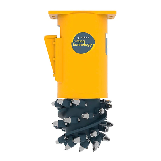
Safety and operating instructions 3.2 Function 3 Overview The operation of a drum cutter is described in a simpli- fied version below: 3.1 Equipment description The drum cutter is an attachment for hydraulic carriers. The illustration gives an overview of the main parts and The cutter drum is powered by the hydraulic motor of the components of the hydraulic attachment. -
Page 17: Modules
Safety and operating instructions Drive, hydraulic motor, intermediate bracket 3.3 Modules Cutter drum The drum cutter is fastened to a suitable adapter plate on the carrier boom via the intermediate bracket (A). The The longitudinal drum cutter is equipped with a cutter intermediate bracket is bolted to the adapter plate. - Page 18 Safety and operating instructions Round attack picks Drilling auger The round attack picks are made of steel and have a The drilling auger (C) can be mounted on the longitudi- brazed tungsten carbide tip. The round attack picks are nal drum cutter as an accessory part. To do so the cutter held in the pick boxes.
-
Page 19: Signs / Labels
Safety and operating instructions 3.4.2 Name plate 3.4 Signs / labels WARNING Missing warnings The name plate and the labels on the hydraulic attach- ment contain important information about the hydraulic attachment and for personal safety. A missing warning can lead to overlooking or misinterpretation of possible risks and cause personal hazards. -
Page 20: Labels
Check that the delivery is complete. Danger zone n Check the delivery for visual damage. No persons should be within n If any defects are found, consult the Epiroc Customer the danger zone. Fragments of Center / dealer in your area. material which come loose... -
Page 21: Standard Round Attack Picks
Safety and operating instructions 3.9 Standard round attack picks Ø Ø Ø Type Ø Ø Ø Locking system Shaft diameter Shaft length Head diameter Head length Tip diameter ER 100 L 20.0 mm 41.0 mm 38.0 mm (1.50 45.0 mm 12.0 mm Retainer sleeve (0.79 in.) (1.61 in.) in.) (1.77 in.) -
Page 22: Tools For Round Attack Picks
Safety and operating instructions 3.10 Tools for round attack picks Set of tools for round attack pick Type ER 100 L ER 250 L ER 400 L ER 450 L ER 600 L ERL 700 ERL 1100 ER 1500 L ER 2000 L A. -
Page 23: Transport
Safety and operating instructions 4.1 Transport using a crane 4 Transport The drum cutter is equipped with transport lugs, for lifting WARNING Hoist tipping over / hydraulic attach- by crane. ment falling n Secure the hydraulic attachment with ropes or chains The hydraulic attachment is heavy. -
Page 24: Transport Using A Forklift Truck
Safety and operating instructions 4.2 Transport using a forklift 4.3 Transport using a truck truck Always transport the drum cutter whilst secured to the assembly stand. Always transport the drum cutter whilst secured to the assembly stand. WARNING Hydraulic attachment tipping over / slipping WARNING Hydraulic attachment tipping over The hydraulic attachment slipping or tipping over and... -
Page 25: Installation
Safety and operating instructions Special conditions apply to using the hydraulic attach- 5 Installation ment at low temperatures (see chapter Low ambient temperature). WARNING Hot hydraulic oil squirting out n Check the oil filter! The hydraulic system is under high pressure. If hydraulic connections come loose or are disconnected, hydraulic An oil filter must be integrated in the tank line of the oil will squirt out under high pressure. -
Page 26: Gear Oil
Safety and operating instructions 5.1.3 Gear oil 5.2 Preconditions for the carrier Temperature Media /consum- Manufacturer The carrier must fulfil the following criteria in order that a range ables drum cutter can be attached to it: • A complete hydraulic hammer or shearer line right to -20 to +30 °C GPD 80 ESSO... -
Page 27: Attaching The Hydraulic Attachment To The Carrier
Safety and operating instructions 5.4 Attaching the hydraulic attachment to the carrier 5.4.1 Mechanical mounting aspects You need an assistant to attach the hydraulic attachment to the carrier. n Agree on hand signals with your assistant, to enable him to help you placing the carrier in the proper posi- tion to attach the hydraulic attachment. -
Page 28: First Installation
Safety and operating instructions n Let your assistant instruct you until the bores in the The adapter plate must not be stopped by mechanical adapter plate (C) and in the stick (D) are properly stops in either position. Consult the authorized Customer aligned. -
Page 29: Making The Hydraulic Connections
Safety and operating instructions NOTICE Damage due to incorrect installed hydraulic 5.4.3 Making the hydraulic connections hoses NOTICE Faulty hydraulic installation Incorrectly installed hydraulic hoses can result in severe The carrier must have a suitable hydraulic installation to damage to property and the environment. The maximum operate the hydraulic attachment. - Page 30 Safety and operating instructions Note: Installation of a hydraulic circuit suitable for operat- First installation / Install separate leakage oil ing a drum cutter on the carrier is the responsibility of the line). Installation of a leakage oil line to drain oil to operator.
-
Page 31: Removing The Hydraulic Attachment From The Carrier
Safety and operating instructions 5.5 Removing the hydraulic WARNING Metal chips shooting off When hammering out bolts, chips may shoot off and attachment from the carrier cause serious eye injuries. n You need an assistant to remove the hydraulic at- u Wear safety glasses when hammering out the tachment. -
Page 32: Exchangeable Attachments
Safety and operating instructions 5.6.1 Mount hexagonal receiver 5.6 Exchangeable attachments not for ERL 700, ERl 1100 With the longitudinal drum cutter there is the option to re- move the cutter drum (see chapter Replace cutter You need an assistant to mount the hexagonal receiver. drum) and install an optional drilling auger. - Page 33 Safety and operating instructions Type Tightening torque ER 250 L 300 Nm (221 ft lbs) ER 400 L 300 Nm (221 ft lbs) ER 450 L 300 Nm (221 ft lbs) ER 600 L 560 Nm (413 ft lbs) ER 1500 L 950 Nm (701 ft lbs) ER 2000 L 1400 Nm (1033 ft lbs)
-
Page 34: Mount Drilling Auger
Safety and operating instructions 5. Fix the fastening screws (P) and nuts (O) and tighten WARNING Risk of fatal injury due to a failure to as required. observe the required tightening torques Accidents can happen due to negligence and these can lead to severe injuries or damage to property. 5.6.3 Mount pivot adapter u Tighten the hexagonal receiver with the required Actual details may differ. -
Page 35: Dismount Pivot Adapter
Safety and operating instructions 5.6.4 Dismount pivot adapter Type Size Tightening torque You need an assistant to remove the pivot adapter. ER 100 L M 20 415 Nm (306 ft lbs) n Place the drum cutter horizontal on a level working ER 250 L M 20 415 Nm (306 ft lbs) -
Page 36: Dismount Hexagonal Receiver And Intermediate Flange
Safety and operating instructions 5.6.6 Dismount hexagonal receiver and intermediate flange not for ERL 700, ERl 1100 n Lift the drum cutter using suitable lifting equipment and suspend on a crane. Observe the weight (see chapter Technical Specifications). n Place the drum cutter upright down a level working area. -
Page 37: Selecting The Correct Drilling Auger
Safety and operating instructions 5.6.7 Selecting the correct drilling auger The selection of the appropriate drilling auger depends on various factors. Prior to attaching the drilling auger, contact the authorized Customer Center / Dealer in your area in order to guarantee optimum working efficiency. The authorized Customer Center / Dealer will advise on the use of suitable tools and the requisite drilling capacity. -
Page 38: Operation
Safety and operating instructions 6 Operation WARNING Lung disease When cutting with the drum cutter, dust harmful to health DANGER Risk of death due to a failure to adhere is generated. Inhaled dust can result in long-term lung to the safety clearance damage or have other effects on health. -
Page 39: Preparations Before Starting
Safety and operating instructions • rock with a high SiO content, when using spray wa- 6.1 Preparations before starting ter and when cutting under water DANGER Fragments flying around • hard rock such as granite, basalt Note: Prior to using the drum cutter in the aforemen- Fragments of material which come loose while operating tioned materials, contact the authorized Customer Cen- the hydraulic attachment may be flung away and can... -
Page 40: Switching The Drum Cutter On And Off
Safety and operating instructions • leak-tightness of all hydraulic connections 6.4 Functional test • feed pressure for both directions of rotation Always carry out a functional test before putting the • pressure in leakage oil line, maximum 3 bar in con- drum cutter into use. -
Page 41: Correct Operation
Safety and operating instructions n Never switch the drum cutter on or off when in con- 6.5 Correct operation tact with the cutting material. n Bring the drum cutter into a raised position. n Check the hydraulic oil temperature regularly when n Switch on the drum cutter and start up. -
Page 42: Prohibited Operation
Safety and operating instructions 6.6.2 Moving the carrier 6.6 Prohibited operation n Never relocate the carrier sideways by placing the n Do not activate the drum cutter with the carrier in hydraulic attachment on the ground to lift the carrier. driving operation. -
Page 43: Impacting/Chopping
Safety and operating instructions 6.6.4 Impacting/chopping n Do not use the hydraulic attachment to impact or chop to destroy material. This would seriously damage the hydraulic attach- ment. 6.7 Activities after use n After use carry out all activities specified in the main- tenance schedule to perform after every shift. -
Page 44: Maintenance
Safety and operating instructions 7 Maintenance WARNING Risk of death due to unauthorised switching on The maintenance work described in the following sec- An unauthorised switching on of the power supply during tions is necessary for the optimum and fault-free opera- maintenance work results in a risk of severe injury and tion of the hydraulic attachment. -
Page 45: Maintenance Works Not Allowed By The Manufacturer
Safety and operating instructions 7.1 Maintenance works not allowed by the manufacturer Some maintenance activities must be carried out exclu- sively by the manufacturer. If such maintenance activi- ties are required, consult the authorized Customer cen- ter / Dealer in your area in order to ensure that they pro- ceed safely. -
Page 46: Maintenance Schedule
Safety and operating instructions 7.2 Maintenance schedule daily, before and after operation Cutter drum / drilling head (drilling auger): Check if all round attack picks exist. Check the round attack picks for wear and play in the pick box. Check the head lengths of all round attack picks for even wear. Check the wear in pick boxes and if necessary the wear sleeves. -
Page 47: Depressurising The Hydraulic System
Safety and operating instructions 7.3 Depressurising the hydraulic 7.4 Cleaning system Clean the drum cutter daily after use. NOTICE Environmental damage due to hydraulic oil Even when you have switched off the carrier, a consider- able residual pressure can still be present in the hy- Hydraulic oil is environmentally harmful and must not draulic system. -
Page 48: Checking Bolted Connections
Safety and operating instructions 7.5 Checking bolted connections 7.8 Change gear oil n Secure the carrier such that it cannot move unexpect- The following maintenance activities are carried out in the workshop. edly. WARNING Risk of injury due to a failure to ob- n Check all bolted connections regularly for tight fit (see serve the minimum clearances Chapter Bolted connections / Tightening torques). -
Page 49: Preparation
Safety and operating instructions 7.8.2 Preparation 7.8.4 Fill up gear oil n Clean the oil filler opening with a cotton cloth. n Fill up gear oil as per the specifications (see chapter Media/consumables). Gear oil volumes (see chapter Technical specifications). Note: It is important to fill until the oil is level with the oil filler screw with the drum cutter in a vertical posi- tion (cutter drums down). -
Page 50: Check The Round Attack Picks And Pick Boxes
Safety and operating instructions 7.9 Check the round attack picks 7.10 Replace round attack picks and pick boxes n You must replace the round attack picks: - if the tungsten carbide tip is worn. Check the round attack picks daily, before and after op- eration. -
Page 51: Replace Round Attack Pick With Knock On Retainer
Safety and operating instructions 7. Place the mounting tool with the knock on retainer (B) 7.10.1 Replace round attack pick with on the pick shaft (D). knock on retainer The following special equipment is required to replace the round attack picks: • Mounting tool for knock on retainer •... -
Page 52: Replace Round Attack Pick With Retaining Sleeve
Safety and operating instructions 5. Clean the pick box. 7.10.2 Replace round attack pick with retaining sleeve 6. Place a new round attack pick (G) in the notch of the puller. The tip of the pick must point in the direction of The following special equipment is required to replace the impact surface (F). -
Page 53: Replace Round Attack Picks With Quick Snap Retainer
Safety and operating instructions 7.10.3 Replace round attack picks with quick snap retainer The following special equipment is required to replace the round attack picks: • Puller tool for pick with quick snap retainer The special equipment is included in the scope of deliv- ery. -
Page 54: Replace Round Attack Picks With Retaining Ring
Safety and operating instructions 7.10.4 Replace round attack picks with retaining ring The following special equipment is required to replace the round attack picks: • Long nose pliers, curved 1. Remove both retaining rings (L) from the pick shaft one after another using long nose pliers (M). 2. -
Page 55: Replace Cutter Drum
Safety and operating instructions n Secure the upright drum cutter against toppling by 7.11 Replace cutter drum suitable means. The following maintenance activities are carried out in n Remove the fastening screws (A) and facing the workshop. screws (B) of the cutter drum. n You must replace the cutter drum: •... -
Page 56: Disassemble Cutter Drum Erl 700, Erl 1100
Safety and operating instructions n Place the cutter drum (E) on a pallet for further use 7.11.2 Disassemble cutter drum ERL 700, and secure against rolling off. ERL 1100 n Remove any clamping sleeves (F) that may remain in Actual details may differ. the cutter drumusing a special extractor (G). n Place the drum cutter on a level working area with sufficient bearing strength. -
Page 57: Assemble Cutter Drum
Safety and operating instructions 7.11.3 Assemble cutter drum You need an assistant to mount the cutter drum. n Agree on hand signals with your assistant, to enable him to help you placing the parts to be attached. WARNING Injury by impacts A sudden movement of the carrier may cause your as- sistant to be hit and injured by the boom or the hydraulic attachment. -
Page 58: Checking Hydraulic Lines
Safety and operating instructions 7.11.3.2 Assemble cutter drum ERL 700, ERL 1100 Actual details may differ. Note: The drum cutter is attached to the carrier. n Place the cutter drum on a level working area with sufficient bearing strength. n Switch on the carrier and push the hexagon of the drive shaft fully into the cutter drum (E). -
Page 59: Checking And Cleaning The Hydraulic Oil Filter Of The Carrier
Safety and operating instructions Note: When working on the hydraulic circuit, always 7.13 Checking and cleaning the have suitable oil receiver tanks available and collect oil hydraulic oil filter of the carrier for environmental reasons. Note: When changing the hydraulic hoses, always use An oil filter must be integrated in the return circuit of the the manufacturer's original parts exclusively. -
Page 60: Bolt Connections / Tightening Torques
Safety and operating instructions 7.16 Bolt connections / Tightening torques The bolt connections of drum cutters are subjected to very high loads. Tighten any loose connections so that the tightening torques are maintained. ER 100 L ER 250 L ER 400 L Connection point Interval Type of spanner / size... - Page 61 Safety and operating instructions The bolt connections of drum cutters are subjected to very high loads. Tighten any loose connections so that the tightening torques are maintained. ER 450 L ER 600 L ERL 700 Connection point Interval Type of spanner / size Tightening torque Adapter plate daily...
- Page 62 Safety and operating instructions The bolt connections of drum cutters are subjected to very high loads. Tighten any loose connections so that the tightening torques are maintained. ERL 1100 ER 1500 L ER 2000 L Connection point Interval Type of spanner / size Tightening torque Adapter plate daily...
-
Page 63: Troubleshooting
Safety and operating instructions 8 Troubleshooting WARNING Risk of injury due to hot surfaces During operation, individual parts of the carrier or drum The following chapter describes the possible causes of cutter can become very hot and cause burns. faults and the procedures to repair them. u Before commencing with troubleshooting, allow hot n In the event of multiple faults arising, reduce the parts to cool to the ambient temperature. -
Page 64: Cutter Drum Does Not Turn / Is Blocked
Safety and operating instructions 8.2 Cutter drum does not turn / is blocked Cause Remedy Cutting material trapped between cut- Shut down machine, depressurise Carrier driver ter drum and drive and safeguard against a restart. Remove trapped cutting material. Allow cutter to run in reverse briefly. Disassemble cutter drum Workshop Hydraulic pump pressure is too low... -
Page 65: Drum Cutter Stops Moving With Light Pressure
Safety and operating instructions 8.4 Drum cutter stops moving with light pressure Cause Remedy Carrier operating pressure too low Check operating pressure and adjust Carrier driver to recommended value. 8.5 Unusual oscillation of the cutter drum Cause Remedy Round attack picks worn, damaged or Replace round attack picks. -
Page 66: Overpressure Cover For The Hydraulic Motor Deformed, Oil Leak On Sealing Surface, Oil Leak At The Pressure Limiting Valve
Safety and operating instructions 8.9 Overpressure cover for the hydraulic motor deformed, oil leak on sealing surface, oil leak at the pressure limiting valve Cause Remedy Pressure in the leakage oil line too Install leakage oil line as per hy- Workshop high. -
Page 67: Repair
Safety and operating instructions 9 Repair n For technical support contact the authorized Cus- tomer Center / Dealer in your area. 9.1 Sending in the hydraulic attachment for repairs NOTICE Mixed hydraulic oil Never mix mineral and non-mineral hydraulic oils! Even small traces of mineral oil mixed in with non-mineral oil can result in damage to both the hydraulic attachment and the carrier. -
Page 68: Storage
Safety and operating instructions 10 Storage Fill hydraulic motor with preservation agent. 10.2 Cutter drum 10.1 Drum cutter n Remove the round attack picks, if the cutter drum are stored for an extended period, (see chapter Replace 10.1.1 Short storage round attack picks). -
Page 69: Disposal
Safety and operating instructions n Dispose of the hydraulic hoses in accordance with 11 Disposal the applicable regulations to avoid environmental hazards. WARNING Risk of injury due to improper disas- sembly Stored residual energy, sharp-edged parts, pointed tips 11.3 Hydraulic oil and corners on or in the machine or on the requisite tools can cause injuries. -
Page 70: Technical Specifications
Safety and operating instructions 12 Technical specifications Type ER 100-2L ER 100-3L ER 100-4L Carrier weight class 3 - 7 t (6600 - 15430 lbs) Service weight 250 kg (551 lbs) Weight without adapter 210 kg (463 lbs) Dimensions Total length 810 mm (31.89 in.) Length of cutter drum 310 mm (12.21 in.) - Page 71 Safety and operating instructions Type ER 250-2L ER 250-3L ER 250-4L Carrier weight class 8 - 15 t (17640 - 33100 lbs) Service weight 410 kg (904 lbs) Weight without adapter 340 kg (750 lbs) Dimensions Total length 1130 mm (44.49 in.) Length of cutter drum 355 mm (13.98 in.) Diameter of cutter drum...
- Page 72 Safety and operating instructions Type ER 400-1L ER 400-2L Carrier weight class 12 - 17 t (26455 - 37479 lbs) Service weight 440 kg (970 lbs) Weight without adapter 365 kg (805 lbs) Dimensions Total length 1130 mm (44.49 in.) Length of cutter drum 355 mm (13.98 in.) Diameter of cutter drum...
- Page 73 Safety and operating instructions Type ER 450-1L ER 450-2L Carrier weight class 12 - 17 t (26455 - 37479 lbs) Service weight 450 kg (992 lbs) Weight without adapter 375 kg (827 lbs) Dimensions Total length 1160 mm (45.67 in.) Length of cutter drum 380 mm (14.96 in.) Diameter of cutter drum...
- Page 74 Safety and operating instructions Type ER 600-1L ER 600-2L Carrier weight class 15 - 22 t (33070 - 48500 lbs) Service weight 660 kg (1455 lbs) Weight without adapter 580 kg (1279 lbs) Dimensions Total length 1340 mm (52.76 in.) Length of cutter drum 550 mm (21.65 in.) Diameter of cutter drum...
- Page 75 Safety and operating instructions Type ERL 700 Carrier weight class 15 - 25 t (33070 - 55116 lbs) Service weight 700 kg (1543 lbs) Weight without adapter 600 kg (1324 lbs) Dimensions Total length 1230 mm (48.43 in.) Length of cutter drum 390 mm (15.35 in.) Diameter of cutter drum 450 mm (17.72 in.)
- Page 76 Safety and operating instructions Type ERL 1100-1 ERL 1100-2 ERL 1100-3 Carrier weight class 25 - 35 t (55116 - 77162 lbs) Service weight 900 kg (1984 lbs) Weight without adapter 660 kg (1455 lbs) Dimensions Total length 1270 mm (50.00 in.) Length of cutter drum 430 mm (16.93 in.) Diameter of cutter drum...
- Page 77 Safety and operating instructions Type ER 1500-0L ER 1500-1L ER 1500-2L ER 1500-3L Carrier weight class 20 - 40 t (44100 - 88200 lbs) Service weight 1450 kg (3197 lbs) Weight without adapter 1200 kg (2646 lbs) Dimensions Total length 1440 mm (56.69 in.) Length of cutter drum 590 mm (23.23 in.)
- Page 78 Safety and operating instructions Type ER 2000-1L ER 2000-2L ER 2000-3L Carrier weight class 35 - 50 t (77162 - 1100231 lbs) Service weight 1800 kg (3968 lbs) Weight without adapter 1500 kg (3307 lbs) Dimensions Total length 1500 mm (59.06 in.) Length of cutter drum 600 mm (23.62 in.) Diameter of cutter drum...
-
Page 79: Technical Specifications Adu
Safety and operating instructions 12.1 Technical specifications ADU Type ADU 100 ADU 250 ADU 450 ADU 600 Carrier weight class 3 - 7 t 8 - 15 t 8 - 17 t 14 - 22 t (6614 - 15432 lbs) (17637 - 33069 lbs) (17637 - 37479 lbs) (30865 - 48502 lbs) - Page 80 Safety and operating instructions Type ADU 700 ADU 1100 ADU 1500 ADU 2000 Carrier weight class 15 - 30 t 18 - 35 t 18 - 40 t 30 - 55 t (33069 - 66139 lbs) (39683 - 77162 lbs) (39683 - 88185 lbs) (66139 - 121254 lbs) Service weight...
-
Page 81: Appendix
Safety and operating instructions 13 Appendix 13.1 Hydraulic installation version 1 for hydraulic hammer min. 5 bar 72.5 PSI - Parts not included in the scope of delivery + Parts included in the scope of delivery HP = high pressure, LP = low pressure A. -
Page 82: Hydraulic Installation Version 2 For Hydraulic Shear Systems
Safety and operating instructions 13.2 Hydraulic installation version 2 for hydraulic shear systems - Parts not included in the scope of delivery + Parts included in the scope of delivery A. Pressure line (High pressure HP) 350 bar (5075 psi) max., Q = X l/min (Y gal/min) B. -
Page 83: Hydraulic Settings (Explanation For Following Diagrams)
Safety and operating instructions 13.3 Hydraulic settings (explanation for following diagrams) Q = Oil flow rate (l/min) n = Cutter drum revolution (rpm) p = Operating pressure (bar) M = Torque at cutter drum (Nm) P = Recommended operating setting (see technical data) 1 = Upper limit of the recommended power range: The drum cutter must not be operated simultaneously at maximum operating pressure and maximum oil flow rate, other- wise the permissible nominal power is exceeded. -
Page 84: Hydraulic Settings Er 100 L
Safety and operating instructions 13.4 Hydraulic settings ER 100 L ER 100-2L Q (l/min) n (rpm) ER 100-3L ER 100-4L Q (l/min) Q (l/min) n (rpm) n (rpm) © Anbaufräsen PC GmbH | 3390 5221 01 | 2020-09-07 Original Instructions... - Page 85 Safety and operating instructions ER 100-2L 5000 1800 4000 3000 2000 1000 Q (gal/min) n (rpm) ER 100-3L ER 100-4L 5000 5000 2000 2400 4000 4000 3000 3000 1000 1200 2000 2000 1000 1000 Q (gal/min) Q (gal/min) n (rpm) n (rpm) ©...
-
Page 86: Hydraulic Settings Er 250 L
Safety and operating instructions 13.5 Hydraulic settings ER 250 L ER 250-2L ER 250-3L Q (l/min) Q (l/min) n (rpm) n (rpm) ER 250-4L Q (l/min) n (rpm) © Anbaufräsen PC GmbH | 3390 5221 01 | 2020-09-07 Original Instructions... - Page 87 Safety and operating instructions ER 250-2 L ER 250-3 L 5000 5000 3000 4000 2000 4000 3000 3000 1500 2000 2000 1000 1000 1000 Q (gal/min) Q (gal/min) n (rpm) n (rpm) ER 250-4 L 4000 5000 4000 3000 2000 2000 1000 Q (gal/min)
-
Page 88: Hydraulic Settings Er 400 L, Er 450 L, Er 600 L
Safety and operating instructions 13.6 Hydraulic settings ER 400 L, ER 450 L, ER 600 L ER 400-1L ER 400-2L ER 450-1L ER 450-2L ER 600-1L ER 600-2L Q (l/min) Q (l/min) n (rpm) n (rpm) 5000 5000 6000 7000 4000 4000 3000 3000 3000 3500 2000 2000 1000... -
Page 89: Hydraulic Settings Erl 700
Safety and operating instructions 13.7 Hydraulic settings ERL 700 ERL 700 Q (l/min) n (rpm) 10000 5000 7500 4000 3000 5000 2000 2500 1000 Q (gal/min) n (rpm) © Anbaufräsen PC GmbH | 3390 5221 01 | 2020-09-07 Original Instructions... -
Page 90: Hydraulic Settings Erl 1100, Er 1500 L
Safety and operating instructions 13.8 Hydraulic settings ERL 1100, ER 1500 L ER 1500-0L ER 1500-1L ERL 1100-1 Q (l/min) Q (l/min) 70 80 n (rpm) n (rpm) ER 1500-2L ER 1500-3L ERL 1100-2 ERL 1100-3 Q (l/min) Q (l/min) 40 50 90 100 n (rpm) n (rpm) ©... - Page 91 Safety and operating instructions ER 1500-0L ER 1500-1L ERL 1100-1 12000 14000 5000 5000 4000 4000 3000 3000 6000 7000 2000 2000 1000 1000 Q (gal/min) Q (gal/min) n (rpm) n (rpm) ER 1500-2L ER 1500-3L ERL 1100-2 ERL 1100-3 15000 5000 5000...
-
Page 92: Hydraulic Settings Er 2000 L
Safety and operating instructions 13.9 Hydraulic settings ER 2000 L ER 2000-1L ER 2000-2L 100 150 200 250 300 350 400 450 Q (l/min) Q (l/min) 20 30 40 50 60 70 80 90 100 110 n (rpm) n (rpm) ER 2000-3L 100 150 200 250 300 Q (l/min) - Page 93 Safety and operating instructions ER 2000-1L ER 2000-2L 5000 5000 18000 14000 4000 4000 3000 3000 12000 7000 2000 2000 6000 1000 1000 Q (gal/min) Q (gal/min) n (rpm) n (rpm) ER 2000-3L 5000 22000 4000 3000 11000 2000 1000 Q (gal/min) n (rpm) ©...
-
Page 94: Ec Declaration Of Conformity (Ec Directive 2006/42/Ec)
Safety and operating instructions 14 EC Declaration of Conformity (EC Directive 2006/42/EC) We, Anbaufräsen PC GmbH, hereby declare that the machines listed below conform to the provisions of EC Directive 2006/42/EC (Machinery Directive), and the harmonised standards mentioned below. Longitudinal drum cutter ER 100-2L ER 450-1L ER 1500-0L... - Page 96 Any unauthorized use or copying of the contents or any part thereof is prohibited. This applies in particular to trademarks, model denominations, part numbers, and drawings. epiroc.com...
Need help?
Do you have a question about the ER-L Series and is the answer not in the manual?
Questions and answers