
Related Manuals for Omron 3G3M1-A4004-ECT


Summarization of Contents
Introduction
Intended Readers
Details on the personnel for whom this manual is intended, focusing on those with electrical systems knowledge.
Notice
Information regarding the correct use of the Multi-function Compact Inverter 3G3M1 Series.
Manual Configuration
Manual Structure
Explains the page structure and the usage of symbol icons within the manual.
Special Information
Classifies and describes special information provided in the manual.
Terms and Conditions Agreement
Warranty, Limitations of Liability
Details Omron's exclusive warranty and limitations on liability for products.
Application Considerations
Discusses suitability of use, programmable products, and responsibilities for application design.
Disclaimers
Covers performance data, change in specifications, and errors and omissions.
Safety Precautions
Indications and Meanings of Safety Information
Explains the precautions and signal words used in the manual for safe use.
Meanings of Signal Words
Defines WARNING and CAUTION signal words and their associated hazards.
Explanation of Symbols
Provides explanations for symbols used to indicate prohibitions, cautions, and compulsory actions.
Precautions for Safe Use
Installation and Storage
Specifies locations to avoid for product installation and storage.
Transportation, Installation, and Wiring
Provides guidelines for safe transportation, installation, and wiring practices.
Operation and Adjustment
Details precautions for safe operation and parameter adjustment.
Precautions for Correct Use
Maintenance and Parts Replacement
Guidelines for maintenance and replacement of parts.
Product Disposal
Instructions on complying with local ordinances and regulations for product disposal.
Warning Label
Highlights the presence and importance of following handling warnings on the product label.
Warning Description
Provides detailed descriptions of the warning symbols and messages.
Items to Check after Unpacking
Checking the Nameplate
Instructions for verifying the inverter model and specifications on the nameplate.
Checking the Model
Details on how to identify the correct model based on its part number and specifications.
Checking the Accessories
Confirms the inclusion of the instruction manual as the only accessory.
Section 1 Overview
1-1 Overview of Functions
Describes the inverter's features, diverse motor control, position control, safety functions, and conventional functions.
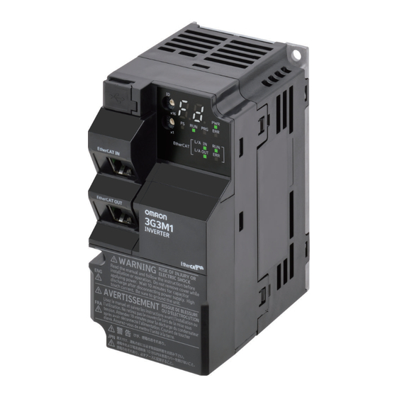
1-2 Appearance and Part Names
Illustrates the front view of the unpacked inverter, identifying key components and terminal blocks.
1-3 Specifications
Details standard specifications, including voltage classes, capacities, and electrical ratings.
1-4 Restrictions
Outlines the availability of functions based on individual control methods and carrier frequency settings.
Section 2 Design
2-1 Installation
Describes inverter installation requirements and the operating environment conditions.
2-2 Removal of Each Part
Details the procedure for removing covers and accessing terminal blocks.
2-3 Wiring
Provides standard connection diagrams and detailed wiring for main and control circuit terminals.
2-4 Others
Covers compliance with EU Directives, UKCA, EMC standards, and wiring precautions.
Section 3 EtherCAT Communications
3-1 Display Area and Settings
Explains the indicators and switches on the inverter's front panel, including node address setting.
3-2 Structure of the CAN Application Protocol over EtherCAT
Details the EtherCAT (CoE) structure for M1-series Inverters with Built-in EtherCAT Communications.
3-3 Communications Status Transitions
Illustrates the EtherCAT State Machine (ESM) transitions and their corresponding SDO/PDO possibilities.
3-4 Process Data Objects (PDOs)
Explains PDOs for real-time data transfer, including mapping settings and Sync Manager assignments.
3-5 Service Data Objects (SDOs)
Lists abort codes for SDO communications errors.
3-6 Synchronization Mode and Communications Cycle
Describes synchronization modes like Free-Run Mode and sets the communications cycle.
3-7 Emergency Messages
Details the structure of emergency messages sent to the master through SDO communications.
3-8 Sysmac Device Features
Describes features provided by the inverter when combined with Machine Automation Controllers.
3-9 Cable Redundancy Function
Explains how configuring a ring topology enables continuous communications even with a disconnected EtherCAT physical layer link.
Section 4 Inverter Control
4-1 Outline
Describes how to use EtherCAT communications to control the inverter via function object selection.
4-2 Control with the Independent Profile
Explains how to use the OMRON profile to control the inverter, including setting parameters and profile allocation.
4-3 Control with the CiA402 Profile
Describes how to use the Velocity mode of the CiA402 drive profile to control the inverter.
4-4 Control with the PDO Free Format
Explains how to allocate objects to PDOs to create an independent profile for advanced control.
Section 5 Operation and Test Run
5-1 Part Names
Shows the names and descriptions of the data display and LEDs on the inverter.
5-2 Connecting Sysmac Studio
Describes how to connect the inverter to the automation software Sysmac Studio for parameter editing and monitoring.
5-3 Flow of Test Run
Provides a step-by-step guide for performing a test run of the inverter.
5-4 Operation Items for Test Run
Details the operation items to be checked during the test run, including installation and power-on procedures.
Section 6 Basic Settings
6-1 Data Initialization
Explains the parameter initialization function to restore factory default settings and clear fault monitor data.
6-2 Setting V/f Control
Describes motor control methods (V/f characteristics) and settings for different load modes.
6-3 Motor Parameter Settings
Details basic parameters for motor control and protection, including induction and PM motors.
6-4 RUN command
Explains how to select the input method for the RUN command, including terminal and EtherCAT control.
6-5 Frequency Reference
Describes methods for setting the frequency reference, including analog input and EtherCAT communication.
6-6 Acceleration/Deceleration Time Settings
Explains how to set acceleration/deceleration time and patterns for controlling motor speed.
6-7 Stop Method Settings
Details the available stop operation methods, including RUN command, external input, and error occurrence.
6-8 Reset
Explains how to use the reset function to reset trip status and clear alarm data.
6-9 Multi-function Input
Describes how to allocate functions to input terminals for operating the inverter.
6-10 Multi-function output
Explains how to allocate functions to output terminals for inverter status monitoring.
6-11 Torque Boost Function Settings
Details the torque boost function for increasing output torque at lower speeds.
6-12 Measures Against Overvoltage
Describes methods to prevent overvoltage by controlling regenerative energy.
Section 7 Vector Control and Applied Functions
7-1 Details of Motor Control Methods
Explains different motor control methods like Dynamic Torque Vector Control, V/f control, and Vector Control.
7-2 V/f control with speed feedback
Describes V/f control with speed feedback using pulse train input and encoder signals for accurate speed control.
7-3 Sensorless Vector Control
Details sensorless vector control for induction motors, enabling high starting torque and improved speed control.
7-4 PM Motor
Explains PM motor control modes, including those with and without speed feedback.
7-5 Speed Control
Describes speed control parameters and functions, applicable to various control methods.
7-6 Torque control
Details the torque control mode settings and functions, including torque limit and bias.
7-7 Position Control
Explains position control functions like basic operation, gains, electronic gear, and overtravel.
7-8 Motor tuning
Provides procedures for motor tuning, including offline auto-tuning for induction and PM motors.
7-9 Brake control function
Describes the built-in brake control function for elevating systems and external brake control.
7-10 Peripheral speed constant control
Explains line speed control settings for winding systems and analog input adjustments.
7-11 Torque limit function
Details the torque limit function for limiting the output torque of the motor.
7-12 Overtorque/Undertorque Function
Describes functions for detecting estimated motor output torque exceeding set levels.
Section 8 Other Functions
8-1 Status Monitors
Describes monitoring functions like output frequency, fault monitor, and torque monitor.
8-2 Multifunction Input/Output Functions List
Lists functions that can be allocated to input and output terminals.
8-3 Analog I/O Settings
Describes analog input and output signal settings, including polarity and scaling.
8-4 Restart Functions
Details restart-related functions and operations, including auto search and momentary power failure.
8-5 DC Injection Braking Function
Explains the DC injection braking function for applying braking according to the load.
8-6 Safety Function
Describes the safety function for stopping the motor by signals from the safety controller.
8-7 Functions Related to Operations
Covers functions related to operations, such as forced terminal block and password functions.
8-8 Functions Related to Protection, Warning and Various Output Signals
Describes protection functions, warnings, and various output signals.
8-9 Other Operation Functions
Details various other operation functions, including carrier frequency and PID control.
Section 9 Troubleshooting
9-1 Alarm Display and Remedies
Explains how to display and reset alarms, including error codes and countermeasures.
9-2 Troubleshooting
Provides a reference for diagnosing and resolving operational issues when no alarm is indicated.
Section 10 Maintenance and Inspection
10-1 Maintenance and Inspection
Describes daily inspection, cleaning, periodic inspection items, and methods.
Appendices
A-1 CiA 402 Drive Profile
Explains the CiA 402 drive profile, including state machine and control commands.
A-2 CoE Objects
Explains the CoE objects implemented in M1-series Inverters, including object dictionary and data types.
A-3 Object List
Provides a comprehensive list of objects with their index, subindex, function name, and data.
A-4 Lists of Manufacturer Specific Objects 2 (Inverter Parameters)
Details manufacturer-specific objects including M, W, Z, X, F, E, C, P, H, J, d, r, and 30xx-hex group parameters.
A-5 Sysmac Error Status Codes
Lists and describes error event codes that can appear in Sysmac Studio.
A-6 Communications Response Time
Lists the communications response time for starting and data transmitting.
A-7 Derating Table
Provides output current derating based on ambient temperature and carrier frequency.
A-8 Smoothing Capacitor Life Curve
Illustrates the relationship between ambient temperature and capacitor life in years.
A-9 Life Alarm Output
Explains the output alarm for consumable parts reaching their end of life.
A-10 Overview of Inverter Selection
Guides the selection of an inverter based on motor capacity and detailed calculation methods.
Need help?
Do you have a question about the 3G3M1-A4004-ECT and is the answer not in the manual?
Questions and answers