
Related Manuals for NAPCO RPXP6GT


Summary of Contents for NAPCO RPXP6GT
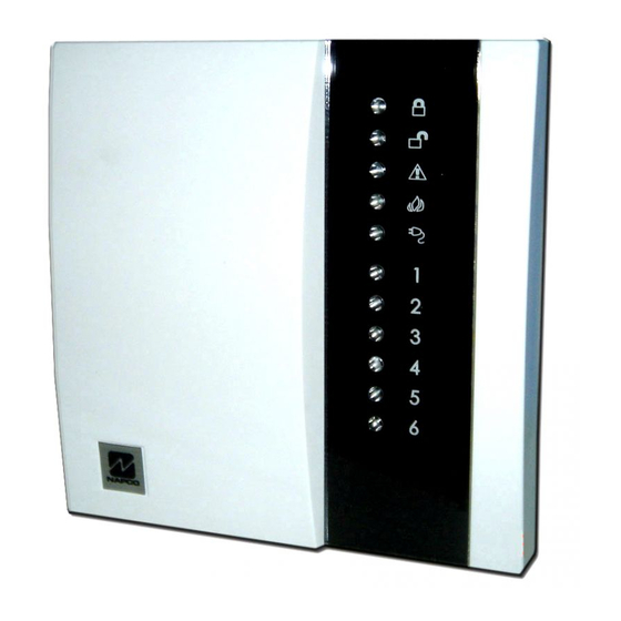
- Page 1 ® XP-600 & RPXP6GT keypad Control Panel/Communicator Installation Instructions WI1372 1/05 © NAPCO 2005...
-
Page 2: Table Of Contents
Wireless ............20 Downloading ............. 21 For Sales and Repairs, call Toll Free: (800) 645-9445 Dealer Programming ......... 22 System Troubles ..........23 Troubleshooting ..........25 For Technical Assistance, Contact the NAPCO Toll Free Helpline XP-600 WIRING DIAGRAM ......27 (800) 645-9440... -
Page 3: Specifications
Bell Output: ----------------------------------- 95 mA Device Specifications (Using Rechargeable 12 VDC 7 AH BATTERY, minimal requirement) Max # keypads: ------------------------------ 4, RPXP6GT current = 65 mA Transformer and Battery Max # of receivers: -------------------------- 2, GEM-RECV-XP8 Required Transformer: -------------------- NAPCO TRF12 OR current = 65 mA each BASLER 16.5 VAC 20VA... -
Page 4: Ul Compatible Smoke Detectors
UL Compatible Smoke Detectors Ordering Information XP-600 Compatible Smoke Detectors XP-600 6 zone Control Panel with 2-wire fire 4-Wire 2-Wire Smoke Detector RPXP6GT Keypad Smoke Detector Smoke Detector Base Zone Doubling Resistor (2.2K & 3.9K) OI301 Operating Instructions XP-600 WI1373... -
Page 5: Programming The Panel
Programming the Panel using PCD2000 Software running PCPreset. 4. Site-Initiated (PCPreset & Site Initiated Downloaded, Auto 5. Automatic Downloading (Using PCPreset) Refer to XP-600 Programming Instructions (WI1373) Download ID Number [93]. Defaulting the Panel Local Downloading 1. Remove power from the panel. 2. -
Page 6: Installation
WI1372 XP-600 Installation Instructions Installation Wiring those required, such as the dining room, bedrooms and utility room. Heat detectors, Mounting the Panel rather than smoke detectors, are recommended Grounding the Panel Mount the Panel close to an unswitched AC kitchens, attics, garages source, a cold-water pipe ground, and a... -
Page 7: Keypad Operation
Burglary Zone Wiring Fire Zone Wiring Keypad Sounder Wire the Fire Zone as shown in the Wiring NAPCO’s EZ Zone Doubling is simple. Each QUICK BEEPS Diagram in the back of this manual. An EOL terminal has 2 zones, use an E (2.2 K) type... -
Page 8: Panel Operation
WI1372 XP-600 Installation Instructions Panel Operation Keypad LEDs 84]. To arm the system with all zones protected, press the key. Press and hold the ARMED LED DEFINITION Arming (System ON) key for 1.5s to fully set the system (the LED Armed Before arming the system close all protected on the Keyfob indicates the Keyfob has... -
Page 9: Bypassing
Delay Tone. Enter a valid Arm/Disarm code. If Home Bypassing a zone a valid Arm/Disarm code is entered, the keypad Press the key, then the zone number to be Exit/Entry Zone is not violated will beep 6 times, indicating the panel has been Zones selected as Home/Away with Delay bypassed. -
Page 10: Xp-600 Commands
WI1372 XP-600 Installation Instructions To change the User 1 Code from its default While in User Program Mode the Armed, specified output. If the battery cannot sustain value of 1234, program the 4-digit User 1 Code READY and SYSTEM Trouble LEDs will the load, a low battery indication will be through Dealer Programming [95]. -
Page 11: Dealer Commands
ready, tell the installer to arm, then disarm. Then + User 1 Code - User Program SIGNAL STRENGTH KEYPAD SOUNDER enter in order to establish a connection. Mode 3 or less S BEEP Phone connection to installer will go "dead" as BEEP Keypad Sleep Mode ON/OFF downloader and panel connect. -
Page 12: Zone Features
WI1372 XP-600 Installation Instructions Zone Features Remote Activation is Entered during Exit Time, Home/Away with Using NAPCO’s Quickloader Software [00]Exit/Entry Zones Delay Zones will be automatically bypassed, even if the (Version 3.26 higher), follow Exit/Entry Zone is violated. Easy Exit/Easy Arm [22-2] must Delay allows exit and entry through an Exit/ be enabled. -
Page 13: System Times
an alarm condition. [07]Burg (Steady) Output [11]Entry Delay Enables the Bell Output on a zone trip for Delay time permits entry through Exit/Entry [04]24-Hour Protection each zone selected. The Bell Output will Zone(s) after the system is armed without A zone that provides protection at all times, remain ON for the length of time setting off an immediate alarm. -
Page 14: System Features
Dealer Mode. The test timer can also be User Code will send an Ambush report offset using NAPCO PCD3000 Downloading when entered to disarm the system. [16]Wireless Supervisory Timer Software. On power up the test timer is sent... -
Page 15: Telephone Number 1 Programming
command. PGM on a Low Battery condition. [22]Miscellaneous Features 1 (3) Follow Keypad Sounder - The following (3) *Trouble - Program to activate the PGM (1) Abort Delay - Program to allow a 15 keypad sounds will activate the PGM output: on a Trouble condition. - Page 16 WI1372 XP-600 Installation Instructions then press the key to blank the last [33]Receiver Options [36]System Reporting, Telco 1 digit. (1) 2300 Hz HS/Kissoff - Select 2300 Hz (1) Keypad Fire - Program to activate a Handshake and Kissoff. Keypad Fire report ( (2) Sumcheck - Only used for the following [31]Telephone Number 1 (2) AUX/AMBUSH - Program to activate an...
-
Page 17: Backup Telephone Programming
Battery Restore report. for Telco 2 (Backup reporting). Refer to break ratio when rotary dialing from 1.5:1 to (3) Trouble Restore - Program to activate a section [32]. 2:1. Trouble Restore report. (3) Backup if < 4 attemps - If Backup Reporting [45-4] has been enabled, the (4) Fire Restore - Program to activate a Fire [43]Receiver Options (Telco 2) -
Page 18: Telephone Number 3 Programming
WI1372 XP-600 Installation Instructions are not transmitted. With this option [1] Fire [7] Gas Alarm selected, a telephone number programmed Digits in Report Codes and subscriber IDs that are [2] Panic [8] Heat Alarm in Leading Digits or Trailing Digits would programmed with "B"... -
Page 19: Enhanced Communicator Features
System Report Code [63]. For example, if a (2) Conditional Closing Telephone 1 - Wireless Low Battery System Report Code is F8 the When enabled, all users that are not Up to two receivers can be wired to the XP- Battery Restore would be E8 (4/2 format). - Page 20 WI1372 XP-600 Installation Instructions Strength Logging Mode - pg. 11). options for each Keyfob. 4 PGM Program a 4 in the AUX 1 and/or AUX 2 AUX 1 & AUX 2 option to activate the PGM Output when the [71-76] Wireless Transmitters Programming Options: buttons on the Keyfob are Enter the RF ID# and the point number that...
-
Page 21: Downloading
Downloading signals received over a two hour period will 8 Interior Program an 8 in the AUX 1 and/or AUX 2 be saved to the LOG. [90]Callback Telephone Number option to Bypass Exit/Entry Follower Zones or Home/Away with Delay Zones when the Program phone number... -
Page 22: Dealer Programming
WI1372 XP-600 Installation Instructions The Computer is now in STANDBY [96]Dealer Options 1 polarity and removes supervision from the bell circuit. (1) Dealer Code Lockout - Program to Site (3) System Trouble Auto Restore - prevent the Dealer Code from changing with At the site perform the following three steps: Normally, System... -
Page 23: System Troubles
System Troubles EXAMPLE on zone 2 would beep the keypad sounder 3 LOW BATTERY SYSTEM TROUBLE times and turn on zone 2 LED. Use the System Trouble chart on the following Press the to enter System Trouble mode and page to determine the specific System Trouble(s). determine the specific trouble. - Page 24 WI1372 XP-600 Installation Instructions System Troubles Keypad Beeps or Zone LED System Trouble Cause/Action SYSTEM Condition Flashes 1 Beep AC Power Failure This trouble will occur if AC power is not present. Ensure that the transformer is connected to an unswitched power source.
-
Page 25: Troubleshooting
Troubleshooting Followers. 6. The PGM Output Pulses in Alarm. Zones programmed for 24 Hour When the PGM lug of the control panel is Protection. To Activate/Deactivate programmed for an Armed indication, it 1. The bell output drops to about 3 volts the chime mode, Press also incorporates... - Page 26 WI1372 XP-600 Installation Instructions 8. How do I remove Keypad Sounder on If using internal reed, make sure J1 is 12. No Keypad Chime? Alarm? cut and both Point 1 and Point 2 The keypad sounder is turned off with the The keypad sounder follows the Burg terminals are jumped out.
-
Page 27: Xp-600 Wiring Diagram
+10 -11 +12 -13 2.2K 16 VAC 20 VA FIRE FIRE BELL +PWR GND GREEN RING RING TRANSFORMER TELCO PHONE NAPCO TRF12 REMOTE BUS (OR EQUIVALENT SEE WI1372). Zone GOLD Class 2 Doubling RED RED Transformer. DO NOT Resistors connect to 3.9K... - Page 28 NAPCO is not an insurer of either the property or safety of the user's family or employees, and limits its liability for any loss or damage including incidental or consequential damages to NAPCO's original selling price of the product regardless of the cause of such loss or damage.
Need help?
Do you have a question about the RPXP6GT and is the answer not in the manual?
Questions and answers
Датчик движения постоянно подает звуковые сигналы хотя в помещении пусто