Table of Contents
Advertisement
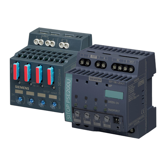
Selectivity modules
SITOP power supply
Selectivity modules
Manual
SITOP select
6EP1961-2BA00
SITOP PSE200U 3A
6EP1961-2BA11
SITOP PSE200U 10 A
6EP1961-2BA21
SITOP PSE200U 3 A
6EP1961-2BA31
SITOP PSE200U 10 A
6EP1961-2BA41
12.2014
C98130-A7579-A1-1-7629
___________________
Overview
___________________
Safety notes
Description, device design,
___________________
dimension drawing
___________________
Mounting/removal
Mounting position, mounting
___________________
clearances
___________________
Installation
___________________
Technical data
___________________
Safety, approvals, EMC
___________________
Environmental conditions
___________________
Environment
___________________
Service & Support
1
2
3
4
5
6
7
8
9
10
Advertisement
Table of Contents

Related Manuals for Siemens SITOP 6EP1961-2BA41


Summarization of Contents
Overview
Product Description and Features
Details the functionality and key benefits of the selectivity module, including its application with 24V power supplies.
Ordering Information for Selectivity Modules
Lists the available selectivity module types, their specifications, and corresponding order numbers.
Safety Notes and Handling
Correct Handling of Devices
Provides crucial safety warnings regarding dangerous voltages and the proper procedures for handling electrical devices.
Description, Device Design, and Dimension Drawing
Device Description and Components
Describes the selectivity module's function, identifying key components like inputs, outputs, LEDs, and potentiometers.
Connections and Terminal Designations
Details the specific input and output terminal designations for different SITOP selectivity module models.
Terminal Data and Wiring Guidelines
Provides specific terminal data, including wire cross-sections, and important wiring notices.
Potentiometer Functionality
Explains the role of the potentiometer in setting the output current response threshold for each channel.
Status Displays and Signaling Methods
Describes the operating status indicators (LEDs) and signaling outputs for various SITOP models.
Buttons and Selector Switches
Details the functions of the buttons and selector switches on the SITOP select and SITOP PSE200U devices.
Manual Output Switching
Explains the procedure for manually switching individual outputs on and off using the device buttons.
Electronic Overload Shutdown and Reset
Explains the electronic overload shutdown mechanism and response characteristics for SITOP select.
Resetting Overload Shutdown via Reset Button
Describes the procedure to reset electronic overload shutdowns using the device's reset button.
Resetting Overload Shutdown via Button and Remote Reset
Explains how to reset electronic overload shutdowns using either the device button or a remote reset signal.
Remote Reset Procedure
Details the functionality and requirements for using a remote reset signal to clear electronic overload shutdowns.
Setting Switch-On Delay Time
Explains how to configure sequential switch-on delay times for outputs to manage inrush currents.
Procedure for Setting Delay Time
Step-by-step guide for setting the switch-on delay time using the reset button and LED feedback.
SITOP PSE200U Selector Switch for Delay Time
Describes how to set the sequential switch-on delay using the DIP selector switch on the SITOP PSE200U.
Block Diagrams of Selectivity Modules
Presents block diagrams illustrating the internal circuitry for different SITOP selectivity module models.
Dimensions and Weight Specifications
Provides detailed dimensional drawings and weight information for the SITOP selectivity modules.
Mounting and Removal
Installation in Housing or Control Cabinet
Instructions for installing the SITOP selectivity modules within a housing or control cabinet for safe access.
Mounting on Standard Mounting Rails
Describes the procedure for securely mounting the device onto standard EN 60715 mounting rails.
Device Removal Procedure
Explains the steps required to safely remove the selectivity module from its mounting rail.
Requirements for Hazardous Zone Installation
Specifies the necessary precautions and enclosure requirements for using the device in hazardous zones.
Mounting Position and Clearances
Standard Mounting Position Requirements
Details the standard vertical mounting position on DIN rails and required clearance space above and below.
Derating Factors for Mounting Height
Explains how installation altitude affects output current and the need for derating.
Derating for Other Mounting Positions
Provides diagrams showing output current derating based on different non-standard mounting orientations.
Installation
Input Side Electrical Connection
Provides instructions and warnings for connecting the 24 V DC power supply to the input terminals.
Output Side Electrical Connection
Details how to connect the loads to the output terminals (OUT 1-4) of the selectivity modules.
Technical Data
Input Specifications
Lists technical data for the input side, including voltage ratings, ranges, and input current.
Output Specifications
Provides technical data for the output side, including output voltage, number of outputs, and adjustable response thresholds.
Output Switching Behavior
Explains how outputs switch on, including simultaneous and sequential options, and overload shutdown characteristics.
Efficiency and Power Loss
Presents data on the efficiency and power loss of the selectivity modules at rated conditions.
Protection and Monitoring Features
Details device protection mechanisms, operating display functions, and signaling capabilities.
Mean Time Between Failures (MTBF)
Provides the Mean Time Between Failures (MTBF) rating for the selectivity modules under specified conditions.
Mechanical System Details
Lists mechanical specifications such as connection systems, housing dimensions, weight, and mounting methods.
Dimension Drawing Data Availability
Information on where to download CAD data for the dimension drawings of the selectivity modules.
Safety, Approvals, and EMC
Safety Standards and Protection Class
Specifies the safety standards (EN 60950-1, EN 50178) and protection class (Class III) for the devices.
Product Approvals and Certifications
Lists key approvals including CE marking, UL/cUL, ATEX, and marine certifications for the selectivity modules.
Electromagnetic Compatibility (EMC)
Details the EMC characteristics, covering emitted interference and noise immunity according to relevant standards.
Environmental Conditions
Ambient Temperature Operating Range
Specifies the operating ambient temperature range and testing conditions for the selectivity modules.
Transport and Storage Temperature Limits
Defines the permissible temperature ranges for transporting and storing the devices.
Humidity Class and Pollution Degree
Specifies the climatic class for humidity and the degree of pollution the device is designed for.
Mechanical Stressing and Damaging Gases
Details mechanical stress resistance (vibration, shock) and testing against damaging atmospheric gases.
Atmospheric Pressure Considerations
Specifies atmospheric pressure ranges for operation and storage, including derating at high altitudes.
Environment and Disposal
Product Compliance and Material Usage
States that devices comply with RoHS and primarily use non-silicon materials.
Disposal Guidelines
Provides guidelines for recycling packaging aids and proper disposal of the product itself.
Service and Support
Technical Support Channels
Information on accessing technical support via phone, email, and online request forms.
Accessing Technical Documentation Online
Links to operating instructions, manuals, and the SITOP power supply homepage for documentation.
Information Material Downloads
Guidance on downloading SITOP-related information material from the Siemens website.
CAx Data Download for Design
Information on obtaining 2D/3D data and circuit diagram macros for engineering and design.
SITOP Selection Tool
Details the SITOP Selection Tool for easily selecting the optimal power supply or DC-UPS.
Online Catalog and Ordering System
Information on accessing the Industry Mall for the online product catalog and ordering system.
Finding Regional Contact Persons
Instructions on how to find and contact regional Siemens sales office representatives for product inquiries.
Need help?
Do you have a question about the SITOP 6EP1961-2BA41 and is the answer not in the manual?
Questions and answers