
Related Manuals for Haier AH1-140B


Summarization of Contents
1.General information
1.1 Function: AHU Valve Box Purpose
Explains AHU valve box function connecting Haier MRV outdoor units with third-party AHUs.
1.2 Feature: Integrated Design and Flexibility
Highlights integrated EXV/control parts, cancelled gas pipes, and flexible installation locations.
1.3 System Lineup Compatibility
Details Haier AHU kit compatibility for MRV5/MRV SII outdoor units across various HP ratings.
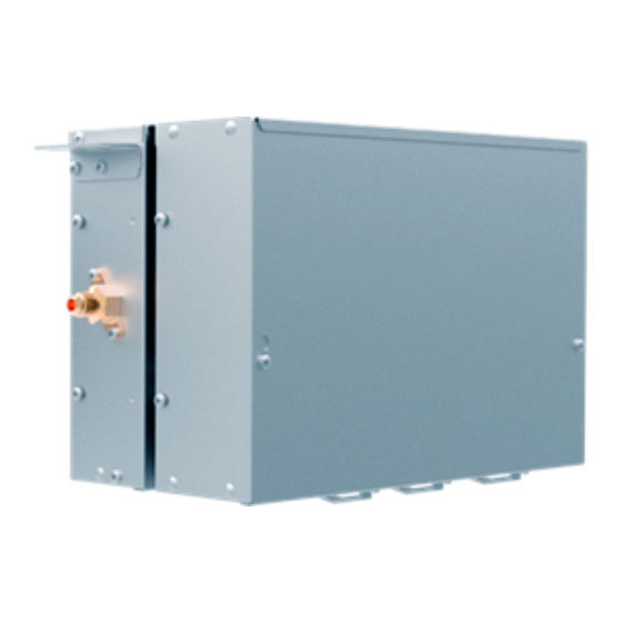
1.4 Configuration Overview
Illustrates the configuration of AH1-070B/AH1-140B/AH1-280B and AH1-560B/AH1-730B models.
1.5 Nomenclature Explained
Explains the coding system for valve box series, type, capacity, and series number.
3. Combination method
Combination Method Details and Notes
Details capacity combinations for AHU valve boxes, models, and notes on pipe length.
4. Dimension
AH1-070B, AH1-140B, AH1-280B Dimensions
Provides detailed dimensional drawings for AH1-070B, AH1-140B, and AH1-280B models.
AH1-560B, AH1-730B Dimensions
Presents detailed dimensional drawings for AH1-560B and AH1-730B models.
5. Wiring diagram
Wiring Diagram Overview
Illustrates the electrical connections and component layout of the AHU valve box.
6.Installation
6.1 Parts and Function
Lists AHU kit components for different models and their respective connections.
6.2 Safety Precautions
Outlines critical safety warnings and precautions for installation and operation.
6.3 Installation Instruction
Provides instructions on installation locations and accessories included with the kit.
6.4 Installation Procedure
Details pre-installation requirements, preparation, and general installation steps.
6.5 Connection Kit Installation
Covers lifting, connection kit installation, and refrigerant pipe installation.
6.6 Temperature Sensor Installation
Sensor Location and Installation Guide
Guides on installing TC1, TC2, and room temperature sensors for optimal performance.
6.7 Electrical wiring
Electrical Wiring Safety and Precautions
Details safety warnings and attention points for proper electrical wiring of the connection kit.
7.PCB photo
PCB Component Identification
Displays an image of the PCB with component labels for reference.
8. Dip switch setting
Address and Capacity DIP Switch Settings
Explains setting wired control addresses and AHU capacity using dip switches.
Communication DIP Switch Settings
Details setting communication and center controller addresses via dip switches for AH devices.
Control Method DIP Switch Settings
Describes setting control methods (Plan A, B, C, D) using dip switches SW1.
AHU Fan Motor Control Methods
Explains controlling AHU fan motor speeds via wired controllers and PCB signals.
9. Failure code
Connection Kit Failure Codes List
Lists error codes (E1-E9) and their corresponding error content for connection kit failures.
10.Troubleshooting
Sensor Fault Troubleshooting Guide
Provides a flowchart for diagnosing and resolving sensor-related faults.
EEPROM and Communication Faults Troubleshooting
Offers troubleshooting steps for EEPROM issues and communication failures between units.
11.Sensor resistance table
Ambient Temperature Sensor Resistance Table
Lists resistance values for the ambient temperature sensor (CN20) at various temperatures.
TC1 and TC2 Sensor Resistance Table
Provides resistance data for TC1 (CN18) and TC2 (CN19) sensors across different temperature ranges.
Need help?
Do you have a question about the AH1-140B and is the answer not in the manual?
Questions and answers