Table of Contents
Advertisement
Quick Links
- 1 Table of Contents
- 2 Installation Quick Tips - Bth 199 and 250 Gas Pressure
- 3 Fault and Warning Conditions - Advanced Diagnostic Information
- 4 Fault Codes
- 5 Controls - Connections, Igniter, Flame Sensor, Sight Glass, Powered Anodes
- 6 Hot Surface Igniter / Flame Sensor / Control Timing
- 7 Wiring Diagram - Bth 120 - 300
- Download this manual
http://waterheatertimer.org/How-to-troubleshoot-gas-water-heater.html
Service Handbook
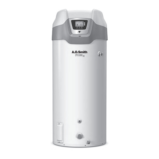
COMMERCIAL GAS HIGH EFFICIENCY WATER HEATERS
MODELS COVERED: BTH 120 THRU 500
SERIES 100, 101 AND
BTH 400/500 SERIES 104
500 Tennessee Waltz Parkway
Ashland City, TN 37015
SERVICING SHOULD ONLY BE PERFORMED BY A QUALIFIED SERVICE TECHNICIAN
PRINTED IN THE U.S.A. 1012
316586-002
Advertisement
Table of Contents

Related Manuals for A.O. Smith BTH 500 Series


Summarization of Contents
Introduction and Qualifications
Introduction to Service Handbook
Provides overview of the service handbook for troubleshooting A.O. Smith commercial water heaters.
Required Service Qualifications
Defines the qualifications and expertise required for servicing the water heater.
General Information and Gas Specifications
General Installation Information
Provides general installation requirements and safety information for the water heaters.
Gas Pressure Specifications
Details gas pressure requirements for different models and gas types.
Gas Supply Systems and Regulators
Gas Supply System Types
Explains low and high pressure gas supply systems and their requirements.
Supply Gas Regulator Installation
Provides instructions on installing and using a positive lock-up gas pressure regulator.
Gas Pressure Adjustment Quick Tips
BTH 120/150 Gas Pressure Adjustment
Guides on adjusting manifold gas pressure for BTH 120 and 150 models.
BTH 199/250 Gas Pressure Adjustment
Details manifold gas pressure for BTH 199 and 250 models, including self-adjustment.
BTH 300/400/500 Gas Pressure Adjustment
Instructions for adjusting manifold gas pressure for BTH 300, 400, and 500 models.
Venting Installation and Materials
Venting Categories and Materials
Describes venting categories and materials used for A.O. Smith commercial water heaters.
Concentric Venting Details
Details concentric venting installation, including pipe length and termination.
Venting Tables and Condensation Management
Venting Length Tables
Provides equivalent feet of intake and vent pipe for BTH models.
Vent Condensation Information
Discusses vent condensation, its effects, and drainage.
Sidewall Vent Terminal Clearances
Power Vent Sidewall Clearances
Specifies sidewall vent termination clearances for power vent installations.
Direct Vent Sidewall Clearances
Specifies sidewall vent termination clearances for direct vent installations.
Direct Vent Terminal Location Requirements
Provides specifications for locating direct vent terminals on a sidewall.
Control System Overview
User Interface Module (UIM) Navigation
Explains the User Interface Module (UIM) and how to interact with the water heater controls.
Status Icon Legend
Provides a legend for status icons displayed on the water heater's UIM.
Temperature and Display Settings
Adjusting Tank Temperature and Set Point
Guides on adjusting tank temperature, operating set point, and differential.
Changing Display Units and Settings
Explains how to change temperature units (Fahrenheit/Celsius) and adjust display settings.
Fault and Warning Diagnostics
Understanding Fault and Warning Conditions
Explains fault and warning conditions detected by the control and how to access advanced diagnostics.
Accessing Current Faults and History
Details how to access and view current fault or warning information and fault history.
Fault Code Reference
Provides a comprehensive list of fault, warning, and error codes for the gas control.
Control Sequence and Flow Chart
Typical Control Sequence Operation
Describes the typical sequence of operation for the water heater's control system.
Control Sequence Flow Chart
Presents a visual flow chart of the water heater's control sequence.
Gas Control Valves and Orifice Charts
Gas Control Valve BTH 120
Describes the gas control valve for BTH 120, including its adjustable regulator.
Gas Control Valve BTH 150
Describes the gas control valve for BTH 150, including its pressure regulator.
Gas Control Valve BTH 199/250
Explains pressure readings for gas control valves on BTH 199/250 models.
Gas Control Valve and Orifice Chart BTH 300-500
Details gas control valves and orifice charts for BTH 300/400/500 models.
Pressure Switch Systems
Pressure Switches All Models Overview
Explains the function of all four pressure switches and their role in safe operation.
Pressure Switch Specifications BTH 120-250
Lists pressure switch specifications for BTH 120 through 250 models.
Pressure Switch Specifications BTH 300-500
Lists pressure switch specifications for BTH 300, 400, and 500 models.
Ignition and Sensing Components
Igniter, Flame Sensor, and Anode Connections
Identifies connections for igniter, flame sensor, and powered anodes.
Igniter, Flame Sensor, and Control Timing
Details hot surface igniter, flame sensor operation, and control timing parameters.
Blower Speed Control Systems
Blower Speed Control BTH 199/250
Explains blower speed control for BTH 199/250 models using Hz settings.
Variable Frequency Drive BTH 400/500
Describes the Variable Frequency Drive (VFD) for blower speed control in BTH 400/500.
VFD Readings for Blower Speed and Pressure
Lists VFD readings for blower speed and pressure for BTH 400/500 models.
Wiring Diagrams
Wiring Diagram BTH 120-300
Provides the wiring diagram for BTH 120 through 300 models.
Wiring Diagram BTH 400-500
Provides the wiring diagram for BTH 400 and 500 models.
Need help?
Do you have a question about the BTH 500 Series and is the answer not in the manual?
Questions and answers