Table of Contents
Advertisement
Quick Links
SERVICE
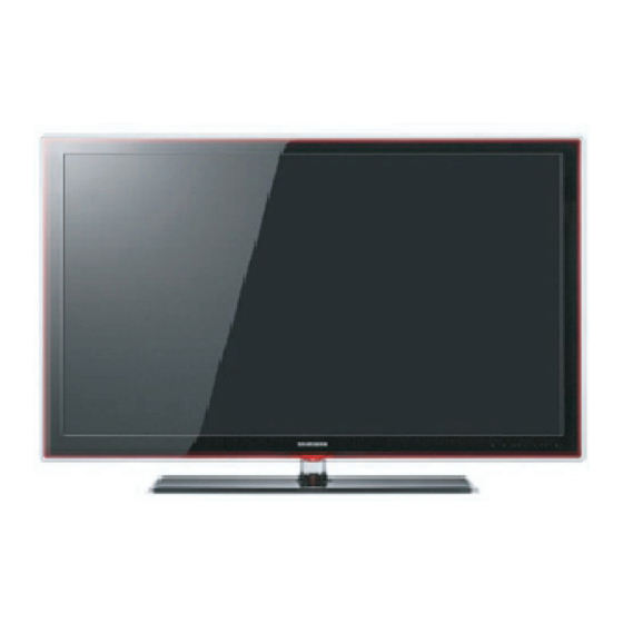
TFT-LED TV
UN32C5000QM / UN40C5000QM / UN46C5000QM
Refer to the service manual in the GSPN (see the rear cover) for the more information.
LED-TV
Chassis :
N98C
Model
:
UN32C5000QM
UN40C5000QM
UN46C5000QM
UN32C4000PM
Manual
1. Precautions
2. Product specifications
3. Disassembly and Reassembly
4. Troubleshooting
5. Exploded View & Part List
6. Wiring Diagram
Contents
Advertisement
Table of Contents

Summarization of Contents
Contents
1. Precautions
Detailed safety and servicing precautions for the LED TV.
2. Product Specifications
Technical specifications and features for various LED TV models.
3. Disassembly and Reassembly
Step-by-step guide for disassembling and reassembling the LED TV.
4. Troubleshooting
Guidance on diagnosing and resolving common issues with the LED TV.
5. Exploded View & Part List
Visual breakdown of TV components and their part numbers.
6. Wiring Diagram
Schematic representation of the TV's internal connections.
1. Precautions
1-1. Safety Precautions
Essential safety, servicing, and ESD precautions to prevent hazards.
1-1-1. Warnings
Important warnings regarding safety and circuit modifications.
1-1-2. Servicing the LED TV
Guidelines for safely servicing the LED TV.
1-1-3. Fire and Shock Hazard
Checks to prevent fire and shock hazards before returning the unit.
1-1-4. Product Safety Notices
Information on special safety-related characteristics of parts.
1. Precautions
1-2. Servicing Precautions
Precautions to follow during servicing procedures.
1-2-1 General Servicing Precautions
General guidelines for safe and effective servicing practices.
1-3. Electrostatically Sensitive Devices (ESD) Precautions
Techniques to prevent damage to components from static electricity.
1. Precautions
1-4. Installation Precautions
Safety precautions to consider during product installation.
2. Product specifications
2-1. Feature & Specifications (UN32C5000QM)
Detailed features and specifications for the UN32C5000QM model.
2. Product specifications
2-1. Feature & Specifications (UN40C5000QM)
Detailed features and specifications for the UN40C5000QM model.
2. Product specifications
2-1. Feature & Specifications (UN46C5000QM)
Detailed features and specifications for the UN46C5000QM model.
2. Product specifications
2-1. Feature & Specifications (UN32C4000PM)
Detailed features and specifications for the UN32C4000PM model.
2. Product specifications
2-2. New Features Explanation
Explanation of the Anynet+ feature and device connection.
2. Product specifications
2-3. Accessories
List of included accessories with their part numbers.
3. Disassembly and Reassembly
3-1. Disassembly and Reassembly (Stand Removal)
Procedure for disassembling and reassembling the TV stand.
3. Disassembly and Reassembly
3-1. Disassembly and Reassembly (Rear Cover)
Steps for removing the rear cover and speaker.
3. Disassembly and Reassembly
3-1. Disassembly and Reassembly (Internal Components)
Steps for removing the stand link, main board, and panel.
4. Troubleshooting
4-1. Troubleshooting
General troubleshooting steps and initial checks.
4-1-1. Previous Check
Initial checks to perform before diagnosing issues.
4. Troubleshooting
4-1-2. No Power
Troubleshooting guide for power-related issues, with diagnostics.
4. Troubleshooting
4-1-3. No Video (Analog PC Signal)
Troubleshooting steps for no video with analog PC input.
4. Troubleshooting
4-1-4. No Video (HDMI1, 2 - Digital Signal)
Troubleshooting for no video with HDMI digital signals.
4. Troubleshooting
4-1-5. No Video (Tuner_CVBS)
Troubleshooting steps for no video with Tuner CVBS signal.
4. Troubleshooting
4-1-6. No Video (Video CVBS)
Troubleshooting for no video with standard CVBS video input.
4. Troubleshooting
4-1-7. No Video (Component)
Troubleshooting steps for no video with Component video input.
4. Troubleshooting
4-1-8. No Sound
Troubleshooting steps for when there is no sound from the TV.
4. Troubleshooting
4-2. Alignments and Adjustments
Instructions for general alignment and adjustment procedures.
4-2-1. General Alignment Instruction
Guidelines for performing general alignment and adjustments.
4. Troubleshooting
4-3. Factory Mode Adjustments
Procedure to enter the service or factory mode using the remote.
4-3-1 Entering Factory Mode
Steps to enter the service mode using the remote control.
4-3-2 How to Access Service Mode
Steps to access the service mode using the customer remote control.
4. Troubleshooting
4-3-3. Detail Factory Option
Specific factory options to change after main board replacement.
4. Troubleshooting
4-3-4. Factory Data
Detailed factory data settings for different models and options.
4. Troubleshooting
ADC/WB Settings
Settings for Analog-to-Digital Converter and White Balance.
ADC Calibration
Calibration procedures for AV, PC, and HDMI inputs.
ADC Target Adjustments
Target values for AV, Component, and PC signal adjustments.
4. Troubleshooting
ADC Result Values
Results of ADC calibration for various signal types.
WB Adjustment Settings
White Balance adjustment settings for brightness and color.
4. Troubleshooting
4-4. White Balance - Calibration
Process for calibrating white balance.
4-4-1 White Balance - Calibration
Steps for calibrating white balance.
4-4-2 White Balance - Adjustment
Steps for adjusting white balance (W/B).
4-5. White Ratio (Balance) Adjustment
Adjusting white ratio in factory mode for optimal display.
4. Troubleshooting
4-6. Servicing Information
Procedure for upgrading TV software via USB or internet.
4-6-1 USB Download Method
Procedure for upgrading TV software via USB or internet.
5. Exploded View & Part List
5-1. UN32C5000QM Exploded View
Exploded view diagram for the UN32C5000QM model.
5-1-1. UN32C5000QM Parts List
List of parts for the UN32C5000QM model.
5. Exploded View & Part List
5-2. UN32C5000QM Parts List
Detailed parts list for the UN32C5000QM model.
6. Wiring Diagram
6-1. Wiring Diagram (UC5000: 40" / 46")
Wiring diagram for UC5000: 40" / 46" models.
6. Wiring Diagram
6-1. Wiring Diagram (UC5000_4000: 32")
Wiring diagram for UC5000_4000: 32" model.
6. Wiring Diagram
6-2. Connector: CN1503, CN301, CN1602, CN1102, CN1101, CN701, CN1304, CN210
Pin assignments for connectors including panel, function, LAN, PC, and power.
6. Wiring Diagram
6-2. Connector: CN1405, CN902, CN901, CN1406, CN1201, CN1202, CN1204, CN1310
Pin assignments for speaker, USB, woofer, HDMI, and monitor out connectors.
6. Wiring Diagram
6-3. Connector Functions
Functionality of specific connectors like CN210 and CN1503.
6-4. Cables
Identification and part numbers for internal TV cables.


Need help?
Do you have a question about the UN40C5000QM and is the answer not in the manual?
Questions and answers