Table of Contents
Advertisement
Advertisement
Table of Contents

Related Manuals for Bigab 12-15 G2


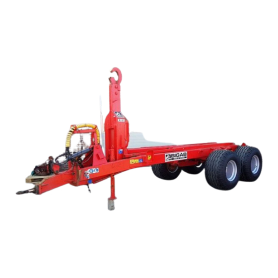
Summary of Contents for Bigab 12-15 G2
- Page 1 www.forsmw.com v1.2 - 2021 - EN Original Instruction Instruction manual...
-
Page 2: Table Of Contents
7–10 8–12 10–14 12–15 14–17 10–14 G2 12–15 G2 TABLE OF CONTENTS IDENTIFICATION OF MACHINE ......................... 2 INTRODUCTION..............................3 SAFETY REGULATIONS ............................4 GENERAL SAFETY INFORMATION ......................4 SAFETY MESSAGES ........................... 4 LOCATION OF THE LABELS ON THE PRODUCT ................5 OPERATION ................................ -
Page 3: Identification Of Machine
7–10 8–12 10–14 12–15 14–17 10–14 G2 12–15 G2 IDENTIFICATION OF MACHINE This instruction manual applies to the BIGAB hooklift trailers 7-10, 8-12, 10-14, 12-15, 10-14 G2, 12-15 G2 and 14-17 and contains information for its safe use. The trailer’s serial number is located on the identification plate and also stamped onto the frame. -
Page 4: Introduction
7–10 8–12 10–14 12–15 14–17 10–14 G2 12–15 G2 INTRODUCTION This Manual gives the owner/operator information about maintaining and servicing the BIGAB hook- lift trailer and provides instruction for safe and proper use of the machine. Even if you have experience of this type of product, we ask that you read and understand the contents of this manual completely and become familiar with your new machine before operating it. -
Page 5: Safety Regulations
It is important for you to train with regard to the trailer’s behaviour. Practice the movement pattern and always work with smaller loads until you are completely familiar with operating the trailer. BIGAB Hooklift is intended for use in agricultural, construction and community work for collection and transportation of waste, scrap, agriculture and other goods. -
Page 6: Location Of The Labels On The Product
LOCATION OF THE LABELS ON THE PRODUCT The BIGAB hooklift trailer is equipped with a range of signs and labels relating to both safety and information of the machine. Check that all the labels are in the correct positions and visible. If signs or labels peel off or get damaged, they must be replaced. - Page 7 7–10 8–12 10–14 12–15 14–17 10–14 G2 12–15 G2 Hazardous movement It is a hazardous movement if the rear end of the tractor lifts. Note! This warning label is included in the delivery of your trailer. It must be attached in a clearly visible location in the tractor cab. If you would like more of these labels, they are available to order, free of charge, from our after sales department.
- Page 8 7–10 8–12 10–14 12–15 14–17 10–14 G2 12–15 G2 Risk of crushing injuries There is a risk of clamping or crushing injuries during work and maintenance. Do not place your hands to the machine or any other moving part. Use the security post during all service operations It is absolutely forbidden to lean under a raised frame unless it is secured with the security post.
-
Page 9: Operation
OPERATION CONTROLS AND DISPLAYS The BIGAB hooklift trailer is only intended to be used and operated from the tractors’ driver seat through the tractor hydraulic lever. Always adapt your operations to your level of experience, current load and road conditions. Do not exceed the trailers maximum travel speed and maximum loading values. -
Page 10: Before Operation
7–10 8–12 10–14 12–15 14–17 10–14 G2 12–15 G2 • Ensure that you have enough space for unloading the product. Wear personal protective equipment such as helmet and footwear. Lifting operator must be certified. • Be careful when unloading and unpacking the trailer: do not damage sensitive components, do not change factory settings or damage paint or other surface finishes. -
Page 11: Connecting Machine
CONNECTING MACHINE Note: When connecting and disconnecting the BIGAB, bear in mind the risk of clamping injuries, the risk of slipping, the tipping risk and the risk of hydraulic high-pressure jets and hot oil. Ensure that neither the hydraulic pump nor the power take-off is connected. - Page 12 HANDLING IN ROLL ON - ROLL OFF Exchange and tipping must be operated from the operator’s seat in the towing vehicle! If your BIGAB is equipped with suspension there is no bogie blocking. Ensure that the trailer is straight in Ensure that the position...
- Page 13 7–10 8–12 10–14 12–15 14–17 10–14 G2 12–15 G2 Follow the movement with the extendable tower so that the front of the hooklift trailer’s frame does not catch on to the rollers. When you have passed the rollers, always keep the hooklift trailer’s frame close to the rollers.
- Page 14 7–10 8–12 10–14 12–15 14–17 10–14 G2 12–15 G2 At maximum load, the telescope must be retracted 40 cm (400 mm) in order for the maximum load to be able to be tipped. Place the hooklift trailer on a flat surface. The sideways incline may not exceed 5 degrees! At maximum tipping angle –...
- Page 15 7–10 8–12 10–14 12–15 14–17 10–14 G2 12–15 G2 Table 1. Example of weight of different types of load Load, kg Kg/m³ Full container 7 m³ 14 m³ 21 m³ 27 m³ Peas, Wheat, water content 15% 5.600 kg 11.200 16.800 21.600 Rye, water content 15%...
-
Page 16: Working In Extreme Conditions
7–10 8–12 10–14 12–15 14–17 10–14 G2 12–15 G2 WORKING IN EXTREME CONDITIONS Recommended working temperature range for a Bigab trailer is from –30°C up to +40°C. Note that working at low temperatures accelerates hydraulic gaskets wear and increases hydraulic hoses exposure to damages and steel constructions exposure to brittle fracture. -
Page 17: Clearing Blockages And Cleaning
• Use an environmentally friendly detergent. Allow it to work for the specified time. Rinse off with hot water; • Always lubricate the BIGAB after cleaning. TRANSPORT The hooklift trailer is meant to be transported attached to the tractor at maximum design speed. - Page 18 7–10 8–12 10–14 12–15 14–17 10–14 G2 12–15 G2 • Never attempt to localize a leakage from hoses or connections by feeling with your hand. The high-pressure oil jet blaze can penetrate skin and cause serious burns and damages. High-pressure oil is also highly flammable; • Avoid getting oil into eyes.
-
Page 19: Daily/Monthly/Yearly Maintenance Procedures And Inspection
7–10 8–12 10–14 12–15 14–17 10–14 G2 12–15 G2 NOTE: Failure to comply with the Fors MW instruction manual invalidates all the machine’s guarantees. Regular, correct maintenance is a precondition for the guarantees applying. NOTE: Only genuine spare parts may be used during repair and maintenance work. DAILY/MONTHLY/YEARLY MAINTENANCE PROCEDURES AND INSPECTION All kinds of maintenance work are subdivided into two groups: operating (preventive) and compulsory (scheduled). - Page 20 7–10 8–12 10–14 12–15 14–17 10–14 G2 12–15 G2 Weekly maintenance: • Tightening of the main cylinder bolts; • Clean the trailer regularly with sponge and soap; • When cleaning never use hot water under high pressure, it will remove the grease from bearings;...
- Page 21 7–10 8–12 10–14 12–15 14–17 10–14 G2 12–15 G2 • After removing the old seals clean the grooves carefully before fitting the new seals into place; • Lubricate the new seals with hydraulic oil; • Open the pistons lock nut; • Screw the piston off;...
- Page 22 7–10 8–12 10–14 12–15 14–17 10–14 G2 12–15 G2 Join and disjoin plug connectors only with dead circuits! Maintenance of the brake system • Control the brakes regularly. Test the brakes at least once per week while trailer is working. • See to it that no lubricant penetrates into the brakes. ...
- Page 23 If the axel for the bogie side is at all moving the trailer is in . Stop at once and tighten the bolts as shown in pictures below. BIGAB tandem parabolic bolts tightening BIGAB sprung pendulum bolts tightening www.forsmw.com...
-
Page 24: Maintenance Materials
7–10 8–12 10–14 12–15 14–17 10–14 G2 12–15 G2 MAINTENANCE MATERIALS NOTE: When changing oil, collect the oil in a safe manner. Never release oil onto the ground. This is prohibited by law. Oil and grease must, by law, also be disposed of at an authorized location. Table 2. -
Page 25: Lubrication Schedule
Bogie bearings, 2 pc *** Roller bearings, 2 pc Back frame bearings, 2 pc Figure 1. Lubrication points of BIGAB * 4 pcs for tandem suspension, 8 pcs for mechanical pendulum bogie,12 pcs for sprung pendulum bogie **Only for tandem suspension ***Only for mechanical pendulum bogie www.forsmw.com... -
Page 26: Storage
7–10 8–12 10–14 12–15 14–17 10–14 G2 12–15 G2 STORAGE If the trailer is not going to be used for an extended period (longer than 2 months) of time, it is important to clean it carefully. Note that high-pressure washing is not recommended. After washing, all the lubricating points must immediately be lubricated. - Page 27 7–10 8–12 10–14 12–15 14–17 10–14 G2 12–15 G2 Table 5. Hydraulic equipment troubles Fault symptoms Reason and action Will not return from working position to Valve stuck. Clean valve parts. Valve should move neutral. freely without seizure. Air in the hydraulic system. Locate leaky point and eliminate defect.
-
Page 28: Technical Information
See main components, roll on-roll off positions and tipping position from figures below. Main components of trailer Roll on - roll off position 7-10 Tipping position 7-10 © 2021 FORS MW Ltd... - Page 29 7–10 8–12 10–14 12–15 14–17 10–14 G2 12–15 G2 Roll on - roll off position 8-12, 10-14, 12-15 and 14-17 Tipping position 8-12, 10-14, 12-15 and 14-17 Roll on - roll off position 10-14 G2 and 12-15 G2 Tipping position 10-14 G2 and 12-15 G2 Hook The trailer is equipped with adjustable hook for three different standard container heights (see figure below).
- Page 30 7–10 8–12 10–14 12–15 14–17 10–14 G2 12–15 G2 Parking leg Parking leg is designed to be supporting when trailer is under maintenance or when trailer is not in use. Standard trailer is equipped with manual parking leg. Hydraulic leg is option. If trailer is at full load then it is not permitted to use the parking leg! Before driving, parking leg must be lifted up and fixed with the...
- Page 31 The trailer can be equipped with wheels as listed in the table. Various alternatives (wheel types) are available - please ask your dealer. Table 7.Wheels, speed limit 40 km/h 10-14 12-15 Wheel type 7-10 8-12 10-14 12-15 14-17 pressure 19/45-17 (ET-70)
-
Page 32: Technical Data
To get exact technical data for your trailer or if you have question, contact your dealer. Maximum speed of the trailer is dependent on the trailer options and country of designation. Hooklift trailer 7-10 Frame (hollow section) 160x80x8 19/45-17; 400/60-15,5;... - Page 33 7–10 8–12 10–14 12–15 14–17 10–14 G2 12–15 G2 Hooklift trailer 8-12 Frame (hollow section) 200x100x6 Wheel dimension 19/45-17; 480/45-17; 400/60-15,5 Requisite tractor hydraulics 1 break outlet; 2 double action Electric system Oil volume *** Trailer weight (kg)* 2200-2400 kg Trailelength (mm)* Min 5790 –...
- Page 34 7–10 8–12 10–14 12–15 14–17 10–14 G2 12–15 G2 Hooklift trailer 10-14 G2 Frame (hollow section) 200x100x6 Wheel dimension 435/50R-19,5; 500/50-17 Requisite tractor hydraulics 1 brake outlet, 3 double action Electric system Oil volume *** Trailer weight (kg)* 2500-2700 kg Trailer lenght (mm)* Min 5790- Max 6400 Width across wheels (mm)*...
- Page 35 7–10 8–12 10–14 12–15 14–17 10–14 G2 12–15 G2 Hooklift trailer 12-15 G2 Frame (hollow section) 200x100x6 Wheel dimension 435/50-19,5; 500/50-17 Requisite tractor hydraulics 1 brake outlet, 4 double action Electric system Oil volume*** Trailer weight (kg)* 2700-2900 Trailer length (mm)* Min 5790- Max 6400 Width across wheels (mm)* 2300...
-
Page 36: Dimensional Drawing
Dimension from ground surface to hook (B) Model\ Mechanical Tandem Sprung Model\ Mechanical Tandem Sprung Suspension pendulum suspension suspension Suspension pendulum suspension suspension 7-10 1066 7-10 8-12 1130 1177 8-12 10-14 1188 1245 1176 10-14 12-15 1188 1245 1176 12-15... -
Page 37: Electrical And Hydraulical System
7–10 8–12 10–14 12–15 14–17 10–14 G2 12–15 G2 ELECTRICAL AND HYDRAULICAL SYSTEM Electrical cable connection Electrical cable connection for rear lights with round 7 pin cable plug Colors according to ISO 1724 Electrical cable connection. Colour Function Yellow (YE) Left turn signal Blue (BU) Fog light... - Page 38 7–10 8–12 10–14 12–15 14–17 10–14 G2 12–15 G2 Rear lights The trailer is manufactured with 12V electrical system. Rear light electrical scheme Table 8. Rear light electrical scheme main components Description Qty. Cable set with plug Right rear lights Left rear lights Connection box Terminal strips 10mm2...
- Page 39 7–10 8–12 10–14 12–15 14–17 10–14 G2 12–15 G2 License plate lights Electrical schemelicense for the plate lights Table 9. Electrical scheme license for the plate lights Description Qty. Rear license plate light PVC cable www.forsmw.com...
- Page 40 7–10 8–12 10–14 12–15 14–17 10–14 G2 12–15 G2 Side marking lights Electrical scheme side for the marking lights Table 10. Electrical scheme side for the marking lights Description Qty. Side marking light PVC cable 15 m Hydraulic system The trailer is equipped with a hydraulic system for operating the functions. All of the hydraulic hoses of the trailer are marked with coloured labels (see figure below).
- Page 41 7–10 8–12 10–14 12–15 14–17 10–14 G2 12–15 G2 Hydraulic hose functions depend on the hydraulic system configuration, see table below: Table 11. Hydraulic hoses marking Color Function mark Yellow Brake Tipping cyl. (up) Blue Tipping cyl. (down) Tower (front) Blue Tower (back) Telescope (in)
- Page 42 7–10 8–12 10–14 12–15 14–17 10–14 G2 12–15 G2 Tipping/rolling BIGAB 7-10 – 14-17 Hydraulic scheme BIGAB 7-10 – 14-17 Table 12.Hydraulic scheme tipping/rolling BIGAB 7-10 - 14-17 Description Description Rubber seal Heat shrink tube Bayonet coupling Stricker Straight nipple...
- Page 43 7–10 8–12 10–14 12–15 14–17 10–14 G2 12–15 G2 Bogie block and frame lock BIGAB 8-12 – 14-17 Table 13. Bogie block and frame lock Description Description Hyd lock H-hose Bolt H-hose Straight nipple H-hose Straight nipple Heat shrink tube...
- Page 44 Dust cover H-hose Angle nipple H-hose Straight nipple H-hose Rubber seal H-hose Straight nipple (choke) H-hose Steerable drawbar 7-10 Table 14. Steerable drawbar 7-10 Description Description Straight nipple Dust cover Rubber seal Heat shrink tube H-hose Sticker Straight nipple Sticker...
- Page 45 7–10 8–12 10–14 12–15 14–17 10–14 G2 12–15 G2 Steerable drawbar BIGAB 8-12– 14-17 Table 15. Steerable drawbar 8-12 – 14-17 Description Description Angle nipple H-hose Rubber seal H-hose Bayonet coupling Heat shrink tube Dust cover Sticker H-hose Hydraulic scheme.Steerable drawbar 8-12 – 14-17...
-
Page 46: Additional Information
7–10 8–12 10–14 12–15 14–17 10–14 G2 12–15 G2 ADDITIONAL INFORMATION CONFORMITY OF STANDARDS The trailer is manufactured according to the demands of the directive 2006/42/EC and therefore can be used mounted together with other equipment to provide a complete machine. WARRANTY The guarantee will only be valid if the reseller as well the buyer signs the Warranty certificate and delivery instruction.
Need help?
Do you have a question about the 12-15 G2 and is the answer not in the manual?
Questions and answers