Table of Contents
Advertisement
Quick Links
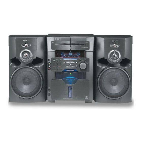
MHC-MG110/MG310AV
SERVICE MANUAL
Ver 1.2 2002.05
• MHC-MG110/MG310AV are composed of following models.
As for the service manual, it is issued for each component model, then, please refer to it.
COMPONENT MODEL NAME
COMPACT DISC DECK RECEIVER SYSTEM
FRONT SPEAKER
CENTER SPEAKER
REAR SPEAKER
SPECIFICATIONS
Power requirements
North American model: 120 V AC,60 Hz
Australian model:
220 – 240 V AC,
50/60 Hz
Power consumption
North American model
MHC-MG310AV:
200 watts
MHC-MG110:
150 watts
Australian model
MHC-MG310AV:
200 watts
Dimensions (w/h/d) incl. projecting parts and controls
Approx. 280 × 383 × 480 mm
Mass
MHC-MG310AV:
Approx. 11.3 kg
MHC-MG110:
Approx. 10.9 kg
Supplied accessories:
Remote commander (1)
Batteries (2)
AM loop antenna (1)
FM lead antenna (1)
Rear speaker cords
(MHC-MG310AV only) (2)
Center speaker pads
(attached to the backside of the center
speaker)
(MHC-MG310AV only) (2)
Video cable (Australian model only) (1)
Design and specifications are subject to change without notice.
Sony Corporation
9-873-800-13
2002E0500-1
Home Audio Company
C 2002.05
Published by Sony Engineering Corporation
MHC-MG110
MHC-MG310AV
HCD-MG110
HCD-MG310AV
SS-MG110
SS-MG510AV
SS-CT360
SS-RS360
PARTS LIST
Part No.
1-476-631-11 REMOTE COMMANDER (RM-SMG5AV) (MG310AV)
1-476-632-11 REMOTE COMMANDER (RM-SMG1) (MG110)
1-501-659-71 ANTENNA (FM) (MG110/MG310AV: US, Canadian)
1-754-060-11 ANTENNA (FM) (Australian)
1-754-102-21 ANTENNA, LOOP (LW.MW)
1-769-433-11 CORD, SPEAKER (10m) (for SS-RS360)
1-823-258-11 CORD, CONNECTION (VIDEO CABLE) (Australian)
4-228-953-01 COVER, BATTERY (for RM-SMG1/SMG5AV)
4-233-902-12 MANUAL, INSTRUCTION (ENGLISH)
4-233-902-22 MANUAL, INSTRUCTION (FRENCH) (Canadian)
4-233-902-31 MANUAL, INSTRUCTION (SPANISH) (Mexican)
MINI Hi-Fi COMPONENT SYSTEM
US Model
Canadian Model
MHC-MG110/MG310AV
Mexican Model
Australian Model
Description
MHC-MG110
MHC-MG310AV
Remark
Advertisement
Table of Contents

Related Manuals for Sony SS-MG110


Summarization of Contents
MHC-MG110/MG310AV Service Manual
Model and Version Information
Identifies model versions and manual revision details.
System Specifications
Details technical specifications for the MHC-MG110/MG310AV system.
Parts List
Lists all replaceable parts with part numbers.
HCD-MG110/MG310AV Service Manual Details
Audio Power Specifications
Details power output and distortion for amplifier sections.
Input/Output and CD Player Specs
Lists input/output signals and CD player performance details.
Servicing Procedures and Safety
Servicing Notes and General Info
General guidelines, precautions, and information for service.
Safety and Handling Precautions
Guidelines for safe component handling, repair, and checks.
Section 1: Servicing Notes
CD-TEXT Test Disc Usage
Procedure for checking CD-TEXT display using a special disc.
Cleaning Optical Pickup Lens
Instructions for safely cleaning the CD player's objective lens.
Section 2: General Information
Parts Identification
Identifies components of the main unit via diagrams and lists.
Remote Control Operations
Setting the Time
Instructions for setting the system's clock time.
Section 3: Disassembly Procedures
Disassembly Flow Chart
Visual guide showing the order of disassembly steps.
Component Disassembly Steps
Detailed instructions for removing major assemblies like covers and boards.
Section 4: Test Modes
Cold Reset and Tuning Interval Change
Procedures for resetting RAM and changing AM tuning interval.
CD Delivery Mode and RAM Initialize
Steps for initializing RAM and entering CD delivery mode.
Key and Display Check Modes
Modes for testing buttons, LEDs, and the indicator tube.
Section 5: Mechanical Adjustments
Tape Mechanism Deck Precautions and Torque
Precautions and torque specs for tape mechanism adjustments.
Head Azimuth and Tape Speed Adjustments
Procedures for adjusting tape head azimuth and speed.
Section 6: Electrical Adjustments
Deck and CD Section Adjustments
Procedures for adjusting tape deck and CD player electrical sections.
Section 7: Diagrams and Schematics
Block Diagrams
System block diagrams illustrating signal flow.
Schematic Diagrams
Detailed circuit schematics for various sections.
Printed Wiring Boards (PWBs)
Layouts of printed wiring boards for component placement.
IC Pin Function Descriptions
Detailed pinouts and functions for integrated circuits.
Section 8: Exploded Views
Exploded Views of Major Assemblies
Visual breakdown of unit parts for identification.
Section 9: Electrical Parts List
Capacitors, Connectors, Diodes, ICs
Lists capacitors, connectors, diodes, and ICs with part details.
Resistors, Switches, Transistors
Lists resistors, switches, transistors, and other components.
Need help?
Do you have a question about the SS-MG110 and is the answer not in the manual?
Questions and answers