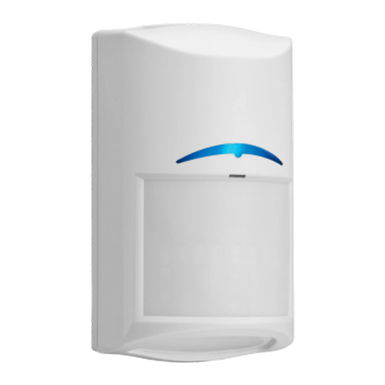
Table of Contents
Advertisement
Quick Links
Advertisement
Table of Contents

Summarization of Contents
Introduction
About documentation
Information about copyright, trademarks, and notifications used in the document.
Bosch Security Systems B.V. product manufacturing dates
Guidance on finding product manufacturing dates using serial numbers and product labels.
Installation
Self-locking cam
Instructions for opening and closing the detector using its self-locking cam mechanism.
Install options
Details on different mounting methods, including direct wall/corner and bracket installation.
Wire knockouts
Identification of various knockouts for wiring during installation.
Bubble level
Using the integrated bubble level for accurate vertical and horizontal alignment during installation.
Wiring
Wiring overview
Overview of the TriTech AM terminal block strip and its connections.
Input Power terminals
Specifications and requirements for connecting the detector's power input.
Alarm terminals
Details on the alarm terminals, including their relay type and operational conditions.
Tamper terminals
Information on tamper terminals and the conditions that trigger a tamper state.
Trouble terminals
Explanation of trouble terminals, their conditions, and potential causes for trouble signals.
EOL resistors overview
Introduction to built-in EOL resistors for simplifying wiring and matching control panel specifications.
Alarm resistors (dip switch section 1)
Using dip switch section 1 for setting alarm EOL resistor values.
Tamper/EOL resistors (dip switch section 2)
Using dip switch section 2 for setting tamper/EOL resistor values for various loop configurations.
EOL resistor loop combinations
Guidance on using external or built-in resistors for different EOL loop configurations.
Single EOL loop - Alarm and Tamper
Wiring diagram for a single EOL loop configuration for alarm and tamper.
Double EOL loop - Alarm and Tamper
Wiring diagram for a double EOL loop configuration for alarm and tamper.
Double EOL loop - Alarm and Tamper with separate Trouble Input
Wiring diagram for a double EOL loop with separate trouble input.
Triple EOL - Alarm, Tamper, and Trouble input
Wiring diagram for a triple EOL loop including alarm, tamper, and trouble inputs.
Configuration
Look-down zone
How to enable or disable the look-down zone using the manual cam for specific detection needs.
Remote LED
Using the RLED input and dip switch for remote control of walk test LED functions on TriTech AM models.
Walk test LED
Understanding the walk test LED indicators for detector status during setup and testing.
Adjustable Cloak and Camouflage Detection Technology sensitivity
Adjusting C²DT sensitivity modes (high/low) for optimal catch performance or false alarm immunity.
TriTech Anti-mask
Information on the TriTech Anti-mask option, applicable only to TriTech AM models.
Walk test
Procedures for performing walk tests to establish PIR and microwave coverage.
Establish the PIR and microwave coverage
Steps for adjusting PIR and microwave coverage using the potentiometer.
Establish the coverage pattern
Methodology for establishing the detector's coverage pattern through walk testing.
Adjustable microwave sensitivity
Using the microwave sensitivity adjustment potentiometer to fine-tune detection range.
Self test
Description of the detector's routine self-test function and troubleshooting for failures.
Troubleshooting
Detector does not appear to respond to motion
Identifies potential causes when the detector fails to respond to motion detection.
Detector is in continuous alarm
Troubleshooting steps for a detector that remains in a continuous alarm state.
Detector appears normal but does not send alarms to the control panel
Diagnosing issues where the detector shows normal operation but doesn't signal the control panel.
Detector does not appear to detect motion in the space directly under it
Addresses issues with detecting motion in the area directly beneath the detector.
Motion detector does not appear to detect motion near the edge of the coverage area
Troubleshooting detection failures at the edges of the detector's coverage area.
Detector does not appear to detect motion in the farther section of the coverage area
Resolving detection issues in the distant parts of the detector's coverage pattern.
Detector LED flashes continuously
Interpreting a continuously flashing detector LED, often related to warm-up or unit failure.
Detector LED flashes two times in a row repeatedly
Understanding the meaning of a detector LED flashing twice, indicating a tamper system failure.
Detector LED flashes three times in a row repeatedly
Diagnosing a detector LED flashing three times, usually indicating a masking attempt.
Detector LED flashes four times in a row repeatedly
Interpreting a detector LED flashing four times, signifying a self-test failure.
Detector LED flashes five times in a row repeatedly
Troubleshooting a detector LED flashing five times, indicating low supply voltage.
Detector LED continually flashing rapidly
Addressing a rapidly flashing detector LED, often due to incorrect mounting orientation.
Coverage patterns
12 meter coverage pattern
Detailed graphical representation of the 12-meter coverage pattern for the detector.
15 meter coverage pattern
Detailed graphical representation of the 15-meter coverage pattern for the detector.


Need help?
Do you have a question about the CDL2-A15H and is the answer not in the manual?
Questions and answers