
Related Manuals for Di-soric SBT-RGB


Summarization of Contents
1 PRELIMINARY NOTE
Foreword and Purpose
This quick guide assists with initial commissioning of di-soric SBx-RGB signal lighting and configuration using a USB IO-Link master.
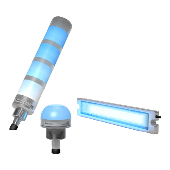
4 NORMAL OPERATION AND APPLICATION AREAS
Reliably Signaling Various Statuses
Ensures safety and reduces response times with professional signaling for prompt fault reaction.
Signal Lighting Applications
Suitable for mechanical engineering, plant construction, intralogistics, and building services engineering.
Ambient Conditions and IP Protection
Industrial suitability with IP protection classes IP20, IP65, and IP67 depending on the variant.
5 OPERATING MODES
External Trigger Mode
Factory default mode using 3 digital inputs for 8 predefined color/lighting configurations without IO-Link.
Operation via IO-Link
Enables Segment, Level, and Demo modes using IO-Link communication for advanced control and configuration.
6 COMMISSIONING
Operation Without IO-Link in External Trigger Mode
Uses 3 digital inputs to activate factory-set presets for lights without IO-Link connection.
Operation with di-soric IO-Link Master
Configure devices using a PC, USB IO-Link Master, and 'IOL Device Tool' software with IODDs.
Operation with Other PLC Online Tools
Utilizes engineering tools like Siemens master with Port Configuration Tool (PCT) for parameterization.
7 PARAMETERIZATION AND CONFIGURATION
Basic Functions
Covers color configuration (8 colors), designation, locator function, and reset to factory settings via specific index variables.
8 OPERATING MODES
8.1 External Trigger Mode
Details trigger mode operation, color selection via digital inputs, and parameterization for presets.
8.2 Segment Mode
Describes segment mode operation, IO-Link process data for color/mode, and parameterization for segments.
8.3 Level Mode
Explains level mode for displaying fill levels and status using foreground/background colors, and parameterization.
9 TROUBLESHOOTING
Error Display
Lists error codes, additional codes, names, and descriptions for troubleshooting signal lighting issues.
Need help?
Do you have a question about the SBT-RGB and is the answer not in the manual?
Questions and answers