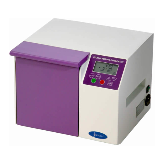
Summary of Contents for seward STOMACHER 400 CIRCULATOR Series
- Page 1 STOMACHER 80/ 400 CLASSIC/ 400 CIRCULATOR/ 3500 Series MAINTENANCE INSTRUCTIONS ® ® ® ® STOMACHER SERVICE AND MAINTENANCE MANUAL...
- Page 2 3. Spare parts number and description list. These sections are all on the CD ROM as separate files in .pdf and .doc format. Please contact SEWARD SERVICE if you have any queries or require advice on any issue: PHONE +44 (0) 1903 236411 +44 (0) 1903 219233 EMAIL info@seward.co.uk...
-
Page 3: Warranty & Service Policy
Seward Ltd are can provide spare parts but are unable to accept any liability implied or otherwise for the incorrect fitting of such parts or cost incurred in the fitting of any replacement parts by third parties. -
Page 4: Routine Servicing
MAINTENANCE INSTRUCTIONS Bush insertion tool - Contact Seward Ltd In the event of difficulty obtaining any item please contact Seward Customer Service. The correct use of hand tools to remove fasteners, wiring terminations and other conventional components is assumed ROUTINE SERVICING... -
Page 5: Troubleshooting
2 hours then run for 5 to 10 minutes with a number of stop/start cycles. 3. Reduce the sample size. 4. Ref.. to section on paddle shaft bearings. In the event of being unable to reach a diagnosis please contact Seward Customer Service. - Page 6 STOMACHER 80/ 400 CLASSIC/ 400 CIRCULATOR/ 3500 Series MAINTENANCE INSTRUCTIONS FAULT DIAGNOSIS CHART No. 1 FAULT DESCRIPTION Instrument Mains Lead will not Connect Connected ? power up Mains Lead Replace Fuse Fuse Failed ? Mains Inlet Replace Fuse(s) Fuse(s) Failed ? Rocker Switch Replace Switch Faulty ?
- Page 7 STOMACHER 80/ 400 CLASSIC/ 400 CIRCULATOR/ 3500 Series MAINTENANCE INSTRUCTIONS FAULT DIAGNOSIS CHART No. 2 FAULT DESCRIPTION Mains Indicator Keypad PCB 'ON' Instrument Connect Connected ? will not run. Is 'LCD' Go to Chart 3 Functioning ? Stall Icon Indicated Go to Chart 4 on LCD ? Press 'RUN'...
- Page 8 STOMACHER 80/ 400 CLASSIC/ 400 CIRCULATOR/ 3500 Series MAINTENANCE INSTRUCTIONS FAULT DIAGNOSIS CHART No. 3 FAULT DESCRIPTION Transformer From Chart 2 12v Fuses Replace Failed ? 12v Supply Check present at Transformer Transformer ? Keypad or Control PCB Faulty...
- Page 9 STOMACHER 80/ 400 CLASSIC/ 400 CIRCULATOR/ 3500 Series MAINTENANCE INSTRUCTIONS FAULT DIAGNOSIS CHART No. 4 Remove obstruction or resolve seizure Replace Fuse FAULT DESCRIPTION PCB Motor Paddles From Chart 2 Protection Jammed or seized ? Fuse Failed ? 110v Supply Check present at Transformer...
- Page 10 STOMACHER 80/ 400 CLASSIC/ 400 CIRCULATOR/ 3500 Series MAINTENANCE INSTRUCTIONS FAULT DIAGNOSIS CHART No. 5 FAULT DESCRIPTION Instrument Keypad PCB runs but at Replace Faulty ? incorrect speed Drive Controller Replace PCB Faulty ? FAULT DIAGNOSIS CHART No. 6 FAULT DESCRIPTION Instrument Keypad PCB runs but for...
- Page 11 STOMACHER 80/ 400 CLASSIC/ 400 CIRCULATOR/ 3500 Series MAINTENANCE INSTRUCTIONS STOMACHER ELECTRONIC SERVICE PROCEDURES To replace the Drive Control PCB remove the rear cover and disconnect the main loom plug and the ribbon cable from the Keypad PCB. Remove the socket cap screws holding the PCB taking care not to cause any damage.
- Page 12 After extreme periods of service it may be necessary to replace the motor brush gear, in this event contact Seward Customer Service for advice. The drive unit is secured to the aluminium motor mounting block by four socket cap screws, DO NOT SLACKEN, unless it is necessary to replace the drive unit.
- Page 13 Avoid damaging the bore if possible. Insert the first new bush using the insertion tool, contact Seward Ltd, insert the second bush ensure the mandrel of the insertion tool passes through the first bush to ensure bore alignment.
- Page 14 STOMACHER 80/ 400 CLASSIC/ 400 CIRCULATOR/ 3500 Series MAINTENANCE INSTRUCTIONS fit. UNDER NO CIRCUMSTANCES should any material be reamed from the bush as this will cause the bush to “bleed” excessive lubricant. Re assemble all components, adjust the paddle clearance. Paddles Clearance Adjustment After carrying out any of the procedures it will be necessary to check and/or adjust the paddle clearance.


Need help?
Do you have a question about the STOMACHER 400 CIRCULATOR Series and is the answer not in the manual?
Questions and answers