Table of Contents
Advertisement
Advertisement
Table of Contents

Related Manuals for AmbiSonic Systems L-300


Summary of Contents for AmbiSonic Systems L-300
- Page 1 LS KITS 3 & 4 Landscape Speaker System Installation Manual LS Kit 3 LS Kit 4...
-
Page 2: Introduction
1. INTRODUCTION Thank you for buying Ambisonic Landscape Loudspeaker system. These systems were designed and tuned by the same engineers who invented multiple speaker satellite/subwoofer outdoor sound systems. They’re built to install easily and quickly, and to sound fantastic day in and day out for years to come. -
Page 3: Table Of Contents
8a. L-300 Amplifier Features (Without Streamer) ......8b. L-300 Amplifier Features (With Streamer) ....... 9. System Planning & Installation ............10a. LS KIT 3 Set Up & Configuration ..........10b. LS KIT 3 L-300 Amplifier Calibration ........11a. LS KIT 4 Set Up & Configuration .......... -
Page 4: Important Safety Instructions
2. IMPORTANT SAFETY INSTRUCTIONS • Read these instructions. • Keep these instructions. • Heed all warnings. • Follow all instructions. • Do not use this apparatus near water. • Clean only with dry cloth. • Do not block any ventilation openings. Install in accordance with the manufacturer’s instructions. - Page 5 • To help maintain ambient temperature, DO NOT mount in locations with direct sunlight. • To reduce the risk of electrical shock, do not open the equipment. For safety reasons it is only allow to the opened by qualified service personnel.
-
Page 6: Warranty
3. WARRANTY Ambisonic warrants to the original retail purchaser only that this Ambisonic product will be free from defects in materials and workmanship, provided the speaker was purchased from an Ambisonic authorized dealer. If the product is determined to be defective, it will be repaired or replaced at Ambisonic’s discretion. -
Page 7: Tools Needed
4. TOOLS NEEDED • Speaker Wire (Burial Grade) • Wire Stripper • Precision Screwdriver • Shovel • Trenching Shovel (Optional) • Rubber Mallet (Optional) 5. SPEAKER CABLE CHOICE Be sure to use burial-grade speaker cable for any cables that will be buried underground. -
Page 8: What's Included
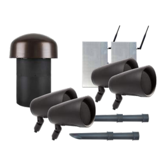
6. WHAT’S INCLUDED a. LS KIT 3 b. LS KIT 4 a. LS KIT 3 b. LS KIT 4 1 x L-300 Amplifier 2 x L-300 Amplifiers 1 x S11BP-IG Burial Subwoofer 1 x S11BP-IG Burial Subwoofer 2 x LS64 Landscape Speakers... -
Page 9: Specifications
7. SPECIFICATIONS LS64 Satellite Speakers: • 6'' Polypropylene Woofer • 6'' Passive Radiator • 1'' Titanium Tweeter • Frequency Response: 60Hz - 20kHz [+/-3dB] • Power Handling: 50W x RMS | 150W Peak • Impedance: 8 Ω or 70 V •... -
Page 10: 8A. L-300 Amplifier Features (Without Streamer)
8a. L-300 AMPLIFIER FEATURES (Without Streamer) MANUFACTURED IN CHINA BRIDGE (70V) SERIAL BARCODE LEFT + RIGHT - SERIAL NUMBER 1. Bluetooth Antenna (1) 2. Bluetooth Switch 3. Bridge (70V) or Stereo Switch 4. Low Pass Filter (LPF) Switch Gain Knob Clipping/BT Indicator Lights Speaker Output: Right Speaker Output: Left... - Page 11 STEREO BRIDGE (70V) GAIN FRONT FACE VIEW LEFT RIGHT UNDERSIDE VIEW...
-
Page 12: 8B. L-300 Amplifier Features (With Streamer)
8b. L-300 AMPLIFIER FEATURES (With Streamer) MANUFACTURED IN CHINA BRIDGE (70V) SERIAL BARCODE 1. Bluetooth Antennas (2) LEFT + RIGHT - SERIAL NUMBER 2. Bluetooth Switch 3. Bridge (70V) or Stereo Switch 4. Low Pass Filter (LPF) Switch Gain Knob Clipping/BT Indicator Lights Speaker Output: Right Speaker Output: Left... - Page 13 STEREO BRIDGE (70V) GAIN FRONT FACE VIEW LEFT RIGHT UNDERSIDE VIEW...
-
Page 14: System Planning & Installation
9. SYSTEM PLANNING & INSTALLATION The speakers and subwoofer should be strategically placed to evenly distribute sound throughout the outdoor area. Fully plan out the locations of the amp, all speakers, subwoofer and buried wires, before beginning the installation process. The system is designed for the speakers to be evenly divided between two PARALLEL wire runs, with the subwoofer connected to both. - Page 15 III. Feed the speaker wire through the top hole of the ground stake and out the wire hole on the side of the stake. Δ The speaker can now be screwed onto the stake clockwise until tight. Δ Using a 4mm hex wrench, adjust speaker angle to the direction of the listening area.
- Page 16 9b. POSITIONING & INSTALLING THE SUBWOOFER I. The S11BP-IG dimensions are 12 3/16'' diameter x 23'' high, 17'' diameter x 18 7/16 Canopy Δ Select a location for the subwoofer. It should be placed as close to the middle of the speaker system as practical, ideally with half the satellite speakers on one side and half on the other.
- Page 17 DIAGRAM 2 • S11BP Subwoofer Burial Installation 17 inch 8.46 23.65 in 5 in 15.75 in 2-4 in 12.09 in 9c. POSITIONING & INSTALLING THE AMPLIFIER Δ Locate a shaded area for the amplifier to be installed out of direct sunlight.
-
Page 18: 10A. Ls Kit 3 Set Up & Configuration
10a. LS KIT 3 | SET UP & CONFIGURATION Running Wires from the Amplifier to the Speaker & Subwoofer I. Dig a 5'' trench where you plan on laying out the wire. Run the left and right speaker cables from the amplifier to the subwoofer location. The subwoofer should have four input connections: Δ... - Page 19 Using waterproof wire nuts, connect both left and right channels from the amp to the subwoofer, making sure positive is connected to positive and negative is connected to negative. DIAGRAM 4 • LS KIT 3 Wiring Diagram CREATE RICH HI-FI 8Ω...
- Page 20 III. Connect the LEFT positive conductor from the amp, to the LEFT positive (White Wire) input on the subwoofer. Connect the LEFT negative conductor from the amp, to the LEFT negative (Green Wire) input on the subwoofer. Δ Left Channel: WHITE = Positive | GREEN = Negative Extend from the subwoofer to the LEFT satellite speaker.
- Page 21 If you wire Positive (+) to Negative (-), the system will not perform as it should. Make all speaker connections and test the system BEFORE burying the wire. 2-Conductor Speaker Cable DIAGRAM 5 • LS KIT 3 Resistor Wiring Diagram (Not Included) FROM SUBWOOFER 8 Ω RESISTOR...
-
Page 22: 10B. Ls Kit 3 L-300 Amplifier Calibration
Once the LS KIT 3 is wired up, follow these Calibration Steps: 10b. LS KIT 3 | L-300 AMPLIFIER CALIBRATION DO NOT ENGAGE BRIDGE MODE FOR ANY OF THE KITS Δ ONLY ENGAGE “LPF” ON THE SUBWOOFER AMP IN KIT 4 Δ... - Page 23 DIAGRAM 6 • L-300 Amplifier Set Up for LS KIT3 FRONT FACE VIEW BLUETOOTH SWITCH STEREO BRIDGE (70V) STEREO STEREO GAIN BRIDGE (70V) BRIDGE (70V) STEREO LEFT RIGHT (70V) BRIDGE BRIDGE (70V) SWITCH [KEEP OFF] STEREO BRIDGE (70V) GAIN GAIN LPF SWITCH [KEEP OFF] 2.
-
Page 24: 11A. Ls Kit 4 Set Up & Configuration
11a. LS KIT 4 | SET UP & CONFIGURATION Running Wires from both Amplifiers: To Speakers & To Subwoofer Dig a 5’’ deep trench where you plan on laying out the wire. Run the left and right speaker cables from the subwoofer amplifier to the subwoofer location. - Page 25 Running Wires from the Subwoofer Amp to the Subwoofer Connect the LEFT positive conductor from the Subwoofer Amp, to the LEFT positive (White Wire) on the subwoofer. Connect the LEFT negative conductor from the Subwoofer Amp, to the LEFT negative (Green Wire) on the subwoofer. III.
- Page 26 Running Wires from the Speaker Amp to the Speakers Connect the LEFT positive conductor from the Speaker Amp to the LEFT positive (Red Wire) on the 1st satellite speaker. Connect LEFT negative conductor from the amp to the LEFT negative (Black Wire) on the satellite speaker.
-
Page 27: 11B. Linking Both Amplifiers For Ls Kit 4
11b. Linking Both Amplifiers for LS KIT 4 Use a 3-conductor wire to make a Phoenix-to-Phoenix Link cable to connect two L-300 Amplifiers. Polarity is critical. L to L, R to R and Center to Center is common. Phoenix connectors are included. Note: The volume adjustment on the second amp will only go as high as the volume on the first amp. -
Page 28: 11C. Ls Kit 4 L-300 Amplifier Calibration
Once the LS KIT 4 is wired up, follow these Calibration Steps: 11c. LS KIT 4 | L-300 AMPLIFIER CALIBRATION Ensure the two L-300 Amplifiers are linked, using the supplied 3 terminal Phoenix connectors, connecting the “Line Out” of the Subwoofer Amp to the “Line In”... - Page 29 DIAGRAM 10 • L-300 Amplifier Set Up for LS KIT4 FRONT FACE VIEW BLUETOOTH STEREO SWITCH BRIDGE (70V) STEREO GAIN STEREO BRIDGE (70V) BRIDGE (70V) STEREO LEFT RIGHT (70V) BRIDGE BRIDGE (70V) SWITCH [KEEP OFF] UNDERSIDE VIEW STEREO BRIDGE (70V) GAIN GAIN LPF SWITCH...
-
Page 30: 12A. Ls Kit 3 Wiring Diagram
12a. LS KIT 3 WIRING DIAGRAM | Approx. 3,000 SQFT COVERAGE S11BP-IG 2 X LS64 L-300 60’ RANGE LEFT CHANNEL RIGHT LEFT CHANNEL CHANNEL CREATE RICH HI-FI RIGHT CHANNEL 8Ω 8Ω SIMPLE, FAST & FLEXIBLE L300 WORKS WITH 2 CHANNELS... -
Page 31: 12B. Ls Kit 4 Wiring Diagram
12b. LS KIT 4 WIRING DIAGRAM | Approx. 3,500+ SQFT COVERAGE S11BP-IG 4 X LS64 60’ RANGE L-300 L-300 L-300 Subwoofer Amp: Engage LPF Only Engage LPF when using L-300 Amp only for Subwoofer [ not on Speaker Amp ] for the LS Kit 4 LEFT CHANNEL LEFT... -
Page 32: Testing The System
13. TESTING THE SYSTEM Get the system playing, then go up close to each of the satellite speakers and the subwoofer to make sure all of them are working. If any one speaker is not working, check the connection for that speaker. If multiple speakers are not working, start by checking the connection for the disconnected speaker that’s closest to the subwoofer, then check the other connections down the line until you get all the satellites... -
Page 33: Troubleshooting
15. TROUBLESHOOTING No sound from all speakers: Make sure the amplifier and source device (bluetooth, music streamer, multi-room controller, etc.) are turned on, music is playing, and the volume is turned up. Check the connections between the source device and the L-300 to make sure they are firmly connected and that the cables are in good condition. -
Page 34: Technical Assistance
If you have any questions or concerns about installing or using this product, you can reach us through one of the following methods: Phone: (844) 674 - 4461 Hours of operation: 8:00am - 5:00pm (Pacific Time), Mon – Fri Email: info@ambisonicsystems.com If you are having technical trouble, please include the model number and briefly explain what steps you took to resolve the problem in your email or be prepared to answer these questions over the phone.
Need help?
Do you have a question about the L-300 and is the answer not in the manual?
Questions and answers