Table of Contents
Advertisement
Quick Links
SERVICE MANUAL
Ver. 1.0 2012.06
• The tuner and CD sections have no adjustments.
(GT575UP only)
FOR UNITED STATES CUSTOMERS. NOT
APPLICABLE IN CANADA, INCLUDING
IN THE PROVINCE OF QUEBEC.
POUR LES CONSOMMATEURS AUX
ÉTATS-UNIS. NON APPLICABLE AU
CANADA, Y COMPRIS LA PROVINCE DE
QUÉBEC.
(GT575UP only)
AUDIO POWER SPECIFICATIONS
CEA2006 Standard
Power Output: 17 Watts RMS 4 at
4 Ohms < 1% THD+N
SN Ratio: 80 dBA
(reference: 1 Watt into 4 Ohms)
Tuner section (GT575UP)
FM
Tuning range: 87.5 – 107.9 MHz
Antenna (aerial) terminal:
External antenna (aerial) connector
Intermediate frequency: 25 kHz
Usable sensitivity: 8 dBf
Selectivity: 75 dB at 400 kHz
Signal-to-noise ratio: 80 dB (stereo)
Separation: 50 dB at 1 kHz
Frequency response: 20 – 15,000 Hz
AM
Tuning range: 530 – 1,710 kHz
Antenna (aerial) terminal:
External antenna (aerial) connector
Intermediate frequency:
9,115 kHz or 9,125 kHz/5 kHz
Sensitivity: 26 μV
9-893-497-01
Sony Corporation
2012F33-1
©
2012.06
Published by Sony Techno Create Corporation
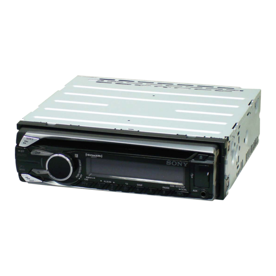
Photo: CDX-GT575UP
Model Name Using Similar Mechanism
Mechanism Type
Optical Pick-up Name
SPECIFICATIONS
MW/LW
Tuner section (GT575UI)
Tuning range:
FM
Tuning range: 87.5 – 108.0 MHz
Antenna (aerial) terminal:
Antenna (aerial) terminal:
External antenna (aerial) connector
Intermediate frequency: 25 kHz
Intermediate frequency:
Usable sensitivity: 8 dBf
Selectivity: 75 dB at 400 kHz
Sensitivity: MW: 26 μV, LW: 45 μV
Signal-to-noise ratio: 80 dB (stereo)
Separation: 50 dB at 1 kHz
CD Player section
Frequency response: 20 – 15,000 Hz
Signal-to-noise ratio: 120 dB
MW/LW
Frequency response: 10 – 20,000 Hz
Tuning range:
Wow and flutter: Below measurable limit
MW: 531 – 1,602 kHz
LW: 153 – 279 kHz
USB Player section
Antenna (aerial) terminal:
Interface: USB (Full-speed)
External antenna (aerial) connector
Maximum current: 1 A
Intermediate frequency:
9,124.5 kHz or 9,115.5 kHz/4.5 kHz
Power amplifier section
Sensitivity: MW: 26 μV, LW: 45 μV
Output: Speaker outputs
Speaker impedance: 4 – 8 ohms
Tuner section (GT575UE)
Maximum power output: 52 W × 4 (at 4 ohms)
FM
Tuning range:
FM1/FM2: 87.5 – 108.0 MHz
(at 50 kHz step)
FM3:
65 – 74 MHz
(at 30 kHz step)
Antenna (aerial) terminal:
External antenna (aerial) connector
Intermediate frequency: 25 kHz
Usable sensitivity: 8 dBf
Selectivity: 75 dB at 400 kHz
Signal-to-noise ratio: 80 dB (stereo)
Separation: 50 dB at 1 kHz
Frequency response: 20 – 15,000 Hz
FM/MW/LW COMPACT DISC PLAYER
CDX-GT575UE/GT575UI/
MW: 531 – 1,602 kHz
LW: 153 – 279 kHz
External antenna (aerial) connector
9,124.5 kHz or 9,115.5 kHz/4.5 kHz
FM/AM COMPACT DISC PLAYER
GT575UP
US Model
Canadian Model
CDX-GT575UP
AEP Model
UK Model
CDX-GT575UI
Russian Model
CDX-GT575UE
CDX-GT565UP/GT565UV
MG-101CA-188
DAX-25A
General
Outputs:
Audio outputs terminal (front, rear/sub
switchable)
Power antenna (aerial)/Power amplifier control
terminal (REM OUT)
Inputs:
SiriusXM input terminal (GT575UP only)
Remote controller input terminal
Antenna (aerial) input terminal
AUX input jack (stereo mini jack)
USB port
Power requirements: 12 V DC car battery
(negative ground (earth))
Dimensions: Approx. 178 × 50 × 177 mm
1
× 2 × 7 in) (w/h/d)
(7
/
8
Mounting dimensions: Approx. 182 × 53 × 160 mm
1
1
5
× 2
× 6
(7
/
/
/
in) (w/h/d)
4
8
16
Mass: Approx. 1.2 kg (2 lb 11 oz)
Supplied accessories:
Remote commander: RM-X211 (GT575UP only)
Parts for installation and connections (1 set)
Design and specifications are subject to change
without notice.
CDX-GT575UP
CDX-GT575UE/GT575UI
Advertisement
Table of Contents

Related Manuals for Sony CDX-GT575UI


Summarization of Contents
SPECIFICATIONS
Tuner section (GT575UP)
FM/AM tuning, antenna, IF, sensitivity, selectivity, S/N, separation, freq. response.
Tuner section (GT575UI)
FM tuning, antenna, IF, sensitivity, selectivity, S/N, separation, freq. response.
Tuner section (GT575UE)
FM1/FM2/FM3 tuning, antenna, IF, sensitivity, selectivity, S/N, separation, freq. response.
CD Player section
S/N ratio, frequency response, and wow/flutter for CD playback.
USB Player section
Interface type and maximum current for USB playback.
Power amplifier section
Speaker impedance and maximum power output for amplifier.
General
Power requirements, dimensions, mass, and supplied accessories.
SERVICING NOTES
Notes on Handling the Optical Pick-Up Block or Base Unit
Warns about electrostatic discharge and careful handling of flexible boards.
Notes on Laser Diode Emission Check
Advises against direct laser viewing and to replace the entire optical pick-up block.
EXTENSION CABLE AND SERVICE POSITION
Note for Replacement of the USB Connector (CN971) and AUX Jack (J901)
Explains the alignment process for replacing USB and AUX connectors on the front panel.
Test Discs
Lists specific test discs required for confirming unit operation and performing checks.
Note for Replacement of the Servo Board
States that the entire servo board should be replaced as individual parts are not repairable.
Note for Replacement of the Sensor Board
Advises exchanging the mechanical block (11CA) ASSY if the sensor board is defective.
Cleaning the Connectors
Provides instructions for cleaning connectors using a cotton swab to ensure proper unit function.
INSTALLATION AND MOUNTING
Mounting Angle Adjustment
Specifies the maximum angle for mounting the unit to ensure proper installation and visibility.
Removing the Protection Collar and the Bracket
Instructions on how to detach the front panel components before installation.
How to Detach and Attach the Front Panel
Details the procedure for removing and reinstalling the front panel of the unit.
Warning if Your Car's Ignition Has No ACC Position
Advises setting the Auto Off function or manually powering down to prevent battery drain.
Fuse Replacement
Instructions on replacing the fuse, emphasizing correct amperage and connection checks.
DISASSEMBLY
Disassembly Flow
Outlines the sequential steps for disassembling the unit.
Mini Fuse (Blade Type) (10A/32V) (FU1), Cover
Details the procedure for removing the mini fuse and cover.
Sub Panel Block
Instructions for removing the sub panel block.
CD Mechanism Deck (MG-101CA-188)
Steps for removing the CD mechanism deck.
Main Board
Procedure for removing the main board, noting destination setting requirement.
Servo Board
Steps for removing the servo board.
Chassis (T) Sub Assy
Instructions for removing the chassis (T) sub assembly.
Roller Arm Assy
Procedure for removing the roller arm assembly.
Chassis (OP) Assy
Instructions for removing the chassis (OP) assembly.
Chucking Arm Sub Assy
Steps for removing the chucking arm sub assembly.
Sled Motor Assy
Procedure for removing the sled motor assembly.
Optical Pick-up Section
Instructions for removing the optical pick-up section.
Optical Pick-up
Details on removing the optical pick-up itself.
DIAGRAMS
Block Diagram - SERVO Section -
Illustrates the functional blocks and connections within the servo section.
Block Diagram - MAIN Section -
Shows the main functional blocks and interconnections of the unit.
Block Diagram - PANEL, POWER SUPPLY Section -
Depicts the block diagram for the panel and power supply sections.
Schematic Diagram - MAIN Section (1/5) -
Part one of the main section schematic diagram.
Schematic Diagram - MAIN Section (2/5) -
Part two of the main section schematic diagram.
Schematic Diagram - MAIN Section (3/5) -
Part three of the main section schematic diagram.
Schematic Diagram - MAIN Section (4/5) -
Part four of the main section schematic diagram.
Schematic Diagram - MAIN Section (5/5) -
Part five of the main section schematic diagram.
Printed Wiring Board - MAIN Section (1/2) -
Component side view of the main board's printed wiring.
Printed Wiring Board - MAIN Section (1/2) -
Conductor side view of the main board's printed wiring.
Printed Wiring Board - KEY Board -
Printed wiring diagram for the key board, showing component layout.
Schematic Diagram - KEY Board -
Schematic diagram detailing the connections on the key board.
IC BLOCK DIAGRAMS
Main Board ICs
Block diagrams for key integrated circuits on the main board (IC301, IC401, IC402, IC603, IC681/682).
Other ICs
Block diagrams for additional ICs, including IC1300 (DC/DC Converter) and IC901 (LCD Driver).
IC PIN FUNCTION DESCRIPTION
Main Board IC501
Detailed pin function description for the main system controller (IC501).
Main Board IC701
Detailed pin function description for the CD head amp, digital servo processor, and audio DSP (IC701).
EXPLODED VIEWS
Main Section
Exploded view of the main section of the unit, showing component parts and their assembly.
Front Panel Section
Exploded view of the front panel section, detailing its parts and assembly.
CD Mechanism Deck Section (MG-101CA-188)
Exploded view of the CD mechanism deck, showing its components.
Need help?
Do you have a question about the CDX-GT575UI and is the answer not in the manual?
Questions and answers