
Related Manuals for OSCILLA TSM500


Summary of Contents for OSCILLA TSM500
- Page 1 USB Calibration Software Instructions for Use Oscilla® USB100-series, USB300-series, SM450-FF, SM930, SM950, TSM400, TSM500, T830 and T840 ID: 993 / ver. 206...
-
Page 2: Table Of Contents
2017-03-22 Table of contents Introduction .............................. 3 Installation of the Oscilla device ......................3 Installation of the software ........................3 General use of the calibration software ....................3 Use of the program with USB1xx, USB3xx and SM450FF ..............4 Air conductor calibration .......................... -
Page 3: Introduction
Run the installation file from the computer, a USB flash stick or a CD drive and start the installation file. Follow the installation windows on the screen, and press Finish on the last window. The software is now installed on your computer and you are ready to calibrate Oscilla instruments. 4 General use of the calibration software Before you beginning the use the calibration software, you must consider two important issues: 1. -
Page 4: Use Of The Program With Usb1Xx, Usb3Xx And Sm450Ff
5 Use of the program with USB1xx, USB3xx and SM450FF Basic operation of the program Start the program and connect the audiometer to the USB port. The program will start at 125 Hz, left channel and 80 dB calibration level, and the tone output will be turned on. -
Page 5: Air Conductor Calibration
Preparing calibration Place the left telephone on the artificial ear and ensure it fits tight. This can be done by selecting 125 Hz, and then position the telephone to get the biggest readout on the calibration equipment. Air conductor calibration By means of the 11 calibration sliders, calibrate the sound pressure for the 11 frequencies to the level set in the... -
Page 6: Free Field Calibration For Sm450-Ff
Free field calibration for SM450-FF The SM450-FF has a free field output, so you are able to connect active speakers or an amplifier to provide passive speakers. The calibration is needed to compensate for the speaker's and test room's nonlinear frequency response. Before doing the free field calibration in the software, the active speakers or the amplifier gain/volume must be on a sensible level. -
Page 7: Use Of The Program With Sm930 And Sm950
6 Use of the program with SM930 and SM950 Basic operation of the program: Start the program and connect the audiometer to the USB port. The program will start at 125 Hz, left channel and 80 dB calibration level, and the tone output will be turned on. The available buttons that appears in program depends... -
Page 8: Air Conductor Calibration
Preparing calibration Place the left telephone on the artificial ear and ensure it fits tight. This can be done by selecting 125 Hz, and then position the telephone to get the biggest readout on the calibration equipment. Air conductor calibration By means of the 11 calibration sliders, calibrate the sound pressure for the 11 frequencies to the level set in the... -
Page 9: Use Of The Program With Tsm400, Tsm500, T830 & T840
7 Use of the program with TSM400, TSM500, T830 & T840 Basic operation of the program: Start the program and connect the tympanometer to the USB port. The program will start at probe tone 226 Hz, 100 dB calibration level, and the tone output will be turned on. The available buttons for tympanometer will appear on the screen. -
Page 10: Calibration Of Probe Tone
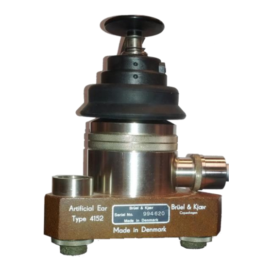
Calibration of probe tone To calibrate the probe tone, an artificial ear with a 2cc coupler is required. Place the probe in a 2cc coupler. Adjust the sliders so all frequencies from 226 Hz to 4 kHz, reach 100 dB SPL. According to IEC 60318-5 ID: 993 / ver. -
Page 11: Pressure Calibration
Pressure calibration To calibrate the pressure sensor, a pressure reference (manometer) must be used to determine the absolute pressure, when calibrating. The manometer must be able to measure at least -500 daPa to +500 daPa with an accuracy of ±0.5%. Follow the guide in the calibration software. 1. - Page 12 4. Read out the positive pressure, and type in the value in the input field and press Next. 5. Read out the negative pressure, and type in the value in the input field and press Next. 6. The pressure calibration is now completed.
-
Page 13: Contralateral Calibration
Contralateral calibration Preparing calibration: Place the contra telephone on the artificial ear and ensure it fits tight. This can be done by selecting 500 Hz, and then position the telephone to get the biggest readout on the calibration equipment. By means of the five calibration sliders, calibrate the sound pressure for the five frequencies to the level set in the Calibration Level box. -
Page 14: Time And Date
Time and date The TSM400, TSM500, T830 and T840 has internal date and time Real Time Clock (RTC). To set this similar to the time and date from the PC, click the button Set Date and Time ID: 993 / ver. 206... -
Page 15: Air Conductor Calibration (Only Tsm500)
Preparing calibration Place the left telephone on the artificial ear and ensure it fits tight. This can be done by selecting 125 Hz, and then position the telephone to get the biggest readout on the calibration equipment. Air conductor calibration (only TSM500) By means of the 11 calibration sliders, calibrate the sound pressure for the 11 frequencies to the level set in the Calibration Level box. -
Page 16: Hearing Level Offsets
8 Hearing level offsets The calibration software currently calibrates to RETSPL values according to IEC 60645-1:2012 or ANSI S3.6-2010. To change between IEC and ANSI values, open the Settings menu and change in the General tab. Click on the ISO button to see the table, if you need <!--RetSPL values 0.0 to 200.0-->... - Page 17 ISO RETSPLs ANSI S3.6-2010 RETSPLs ID: 993 / ver. 206...
-
Page 18: Spl Or Hl Calibration Mode
9 SPL or HL calibration mode The software is set to SPL mode, by default. Open the Settings menu to change the calibration mode between HL and SPL. In SPL mode, all corrections and RETSPL values are included automatically, i.e. 80 SPL in the calibration software results in a read out of 80 SPL on the level meter, assuming microphone and mastoid corrections are entered in the software correctly. -
Page 19: Hl Mode
HL mode Target for TDH39 earphone: RETSPL Microphone ISO 389-1 Correction Attenuator Target [dB] [dB] [dB] [dB] 45,0 0,05 95,05 25,5 0,00 95,50 11,5 91,48 -0,02 -0,01 87,49 1000 0,01 87,01 1500 0,04 86,54 2000 0,11 89,11 3000 10,0 0,25 90,25 4000 0,40... -
Page 20: Spl Mode
SPL mode Air: When calibrating an audiometer with TDH-39, at 80 dB SPL on 250 Hz from the calibration software, the dB level meter will also show 80 dB SPL. 80 dB SPL If you start up the AudioConsole software, and start a tone on 80 dB HL, the dB level meter will also show 105,5dB SPL, i.e. -
Page 21: Calibration Certificate
10 Calibration certificate Press the Certificate button to produce a calibration certificate for the device after the calibration is finished. If you have a free field audiometer and have done the Free field calibration too, remember to check mark the Free field calibrated. -
Page 22: Correction Values For Microphone And Mastoid
11 Correction values for microphone and mastoid To make the calibration of the audiometer easier, there is an option to type in the frequency-dependent dB- corrections for the microphone and mastoid. This will allow you to calibrate to same SPLs and VFLs for each frequency. -
Page 23: Calibration Equipment Information
12 Calibration equipment information In order to get the type and serial numbers for calibration equipment on the calibration certificate, you have to enter this information in the calibration software. Click on Settings and on Calibration equipment tab: ID: 993 / ver. 206... -
Page 24: Responsibility Of The Manufacturer
13 Responsibility of the manufacturer The manufacturer is only responsible for the safety, reliability and performance of the device if: All assembly operations, extensions, re-adjustments, modifications or repairs are carried out by the device manufacturer or by personnel authorized by the manufacturer. The electrical installation, to which the device is connected, complies with EN/IEC requirements.
Need help?
Do you have a question about the TSM500 and is the answer not in the manual?
Questions and answers