Advertisement
Quick Links
Advertisement

Related Manuals for OSCILLA SM960-C


Summary of Contents for OSCILLA SM960-C
- Page 1 ID: 1745 / ver. 201...
- Page 2 Table of content: 1. GAIN CONSTANT adjustment (mode1) ..............4 2. INPUT adjustment (mode 2) ..................5 3. OUTPUT adjustment (mode 3) ..................6 4. LEVEL OFFSETS adjustment (mode 4) ..............8 5. SENSOR CORRECTIONS (mode 5) ..............11 ID: 1745 / ver. 201...
- Page 3 Due to tolerances of the transducers and the hardware, it is necessary to adjust the audiometer’s output signal to the correct level. The adjustment is done with the telephones, bone conductor, insert phones and freefield speaker the audiometer is used with. If one of the transducers is replaced, the audiometer should be adjusted again, with the new transducer.
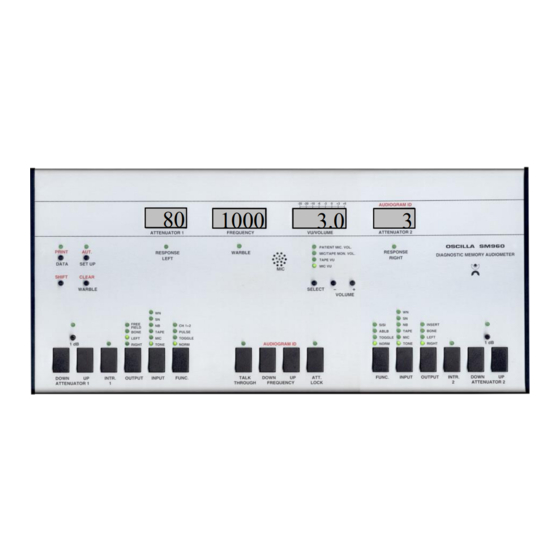
- Page 4 1. GAIN CONSTANT adjustment (mode1) This adjustment is to ensure that the attenuators attenuation is accurate at both large and small attenuations. The adjustment is done at 1000 Hz through bandpass filter. Use the frequency keys to choose between 20, 40, 60, 80 and 100 dB. The adjustment is Left done with the channel 1 attenuator.
- Page 5 2. INPUT adjustment (mode 2) This is used to adjust the five different input signal levels in relation to each other. Choose the signal type with the channel 1 input selector, and do the adjustment with the channel 1 attenuator: Vollume buttons on the front Tone TAPE...
- Page 6 3. OUTPUT adjustment (mode 3) Used to calibrate the levels of telephones, bone conductor, insert Tone phones and free field speaker. Choose the output to calibrate Insert with the output selectors. The right, left, bone and mono insert Tone outputs are selected on channel 2, and free field is selected on channel 1.
- Page 7 Adjust sound level: Adjustment of sound level is done at 80 dB, as default. However, if another calibration level is desired, it may be changed by holding down the SHIFT button while pressing the channel 1 attenuator keys. The actual calibration is done with the attenuator keys, without holding SHIFT. When calibrating, a dB udstyrnumber is shown in the VU display.
- Page 8 4. LEVEL OFFSETS adjustment (mode 4) RETSPL table for TDH39 telephone (ISO-389-1995) 25.5 11.5 1000 1500 2000 3000 4000 6000 15.5 8000 RETSPL table for DD45 telephone 45.5 1000 1500 2000 3000 4000 12.5 6000 18.5 8000 Narrow band masking The masking level should be 3 dB higher than the tone’s, at all frequencies.
- Page 9 Adjustment Read the tone’s sound level. Select noise with the channel 2 input selector. Adjust, with the channel 1 attenuator, so that the average level is 3 dB higher than the tone’s. Repeat the adjustment of tone and masking with the right telephone. Use the channel 2 output selector to choose right channel. Adjustment of the stereo insert phones A set of stereo insert phones may be connected to the same outputs as the normal phones.
- Page 10 Adjustment of the bone conductor Adjustment of the bone conductor is done at 60 dB, as default. As for the telephones, this default level can be changed by holding SHIFT while pressing the attenuator keys. The adjustment should be done through a bandpass filter.
- Page 11 Narrow band masking Perform the same adjustment for narrow band masking levels, as for the telephones. Adjustment of the mono insert telephone The mono insert phone should be adjusted to the same levels as the normal telephones. The procedure is the same as for the telephones. Use the output 2 output selector to select the mono insert phone. Calibration of insert phones requires a special acoustic coupler, for example the Brüel &...
Need help?
Do you have a question about the SM960-C and is the answer not in the manual?
Questions and answers