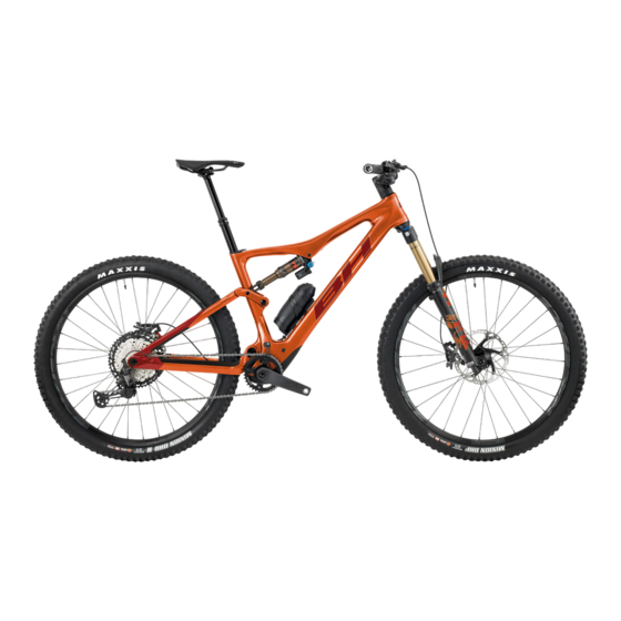
Summarization of Contents
01 INTRODUCTION AND SAFETY
SYMBOLS AND THEIR MEANINGS
Icons for warnings and their meanings.
SAFETY PRECAUTIONS
Definitions of DANGER, WARNING, ATTENTION, and electrical risks.
REQUIRED TOOLS FOR ASSEMBLY
List of tools required for assembly and maintenance.
ASSEMBLY COMPOUND TYPES
Types of grease, oil, and paste for assembly.
02 BH WARRANTY
STATUTORY WARRANTY DETAILS
Legal warranty coverage and conditions.
LIFETIME FRAME WARRANTY PROGRAM
Details of the extended lifetime frame warranty.
EXTENDED WARRANTY PROGRAMS
EXTENDED WARRANTY ON BH MOTORS
5-year warranty for BH motors.
EXTENDED WARRANTY FOR BH BATTERIES
Extended warranty for BH batteries.
WARRANTY REGISTRATION AND CLAIMS
REGISTERING EXTENDED WARRANTIES
Process to activate extended warranties.
WARRANTY OF ELECTRICAL PARTS
Warranty for electrical assistance system components.
SUBMITTING A WARRANTY CLAIM
Procedure for submitting a warranty claim.
CONDITIONS VOIDING ELECTRICAL WARRANTY
Factors that invalidate electrical component warranty.
03 MAINTENANCE
PRE-RIDE INSPECTION CHECKLIST
Essential checks before riding the bicycle.
BICYCLE CLEANING GUIDELINES
Recommended cleaning procedures for the bike.
TRANSMISSION LUBRICATION ADVICE
Importance and method of lubricating the transmission.
PART MAINTENANCE OVERVIEW
General overview of bike maintenance.
SPARE PARTS GUIDANCE
TYRE REPLACEMENT ADVICE
Guidelines for replacing bicycle tyres.
INNER TUBE REPLACEMENT
Guidelines for replacing inner tubes.
DISC BRAKE PAD REPLACEMENT
Advice for disc brakes and pads.
LIGHT REPLACEMENT GUIDANCE
Guidance on replacing lights.
04 WARNINGS ON USE
POST-IMPACT INSPECTION PROCEDURE
Checks after a fall, blow, or impact.
DIMENSIONAL LIMITATIONS AND CHECKS
Limits for tyre size, seat post, fork, and steering components.
INTENDED USE GUIDELINES
Defines the bicycle's intended use and limits.
05 WARNINGS ON ELECTRICAL ASSISTANCE SYSTEM
ELECTRICAL SYSTEM CARE AND SAFETY
Covers component care, battery life, usage, and charging environments.
BATTERY RECYCLING AND MOTOR INFO
Battery recycling and motor lifespan details.
06 PEDAL ASSISTANCE SYSTEM OPERATION
SYSTEM COMPONENTS OVERVIEW
Identification of key pedal assistance system parts.
PEDAL ASSISTANCE SYSTEM FUNCTION
How the assisted pedaling system operates.
CONTROL PANEL LAYOUT AND FUNCTION
Description of the i-Remote control panel and its functions.
SYSTEM POWER MANAGEMENT
How to turn the pedal assistance system on/off.
ASSISTANCE MODES AND STARTING PROCEDURES
BICYCLE LIGHT CONTROL OPERATION
Operation of bicycle lights.
ASSISTANCE MODE SELECTION GUIDE
How to choose different assistance levels.
WALK ASSIST MODE FUNCTION
Functionality of the walk assist mode.
STARTING TO PEDAL SAFELY
Guidance for safe pedaling initiation.
BATTERY LEVEL DISPLAY AND TECHNOLOGY
CENTRAL DISPLAY OF BATTERY LEVEL
Checking battery status via the control panel.
EXTERNAL BATTERY DISPLAY
Checking external battery charge level.
BATTERY AND CHARGER TECHNOLOGY
Information on battery tech and chargers.
BATTERY CHARGING GUIDELINES
Recommendations for charging the battery.
CHARGING PROCEDURES AND SAFETY PRECAUTIONS
STEP-BY-STEP CHARGING GUIDE
Instructions for charging the battery.
CHARGING SAFETY PRECAUTIONS
Important safety warnings during charging.
XPRO EXTERNAL BATTERY AND ENERGY MODES
XPRO EXTERNAL BATTERY FUNCTION
Description of the Xpro external battery.
XPRO BATTERY CHARGING PROCESS
How to charge the Xpro battery.
XPRO BOTTLE HOLDER DETAILS
Details on the Xpro battery bottle holder.
ENERGY SAVING MODES EXPLAINED
Explanation of Transport, Standby, and Deep Sleep modes.
CONNECTIVITY: APP AND GARMIN DEVICE
BH BIKES ICONNECT APP USAGE
Customizing settings with the mobile app.
GARMIN DEVICE INTEGRATION
Connecting and using the bike with a Garmin device.
SOFTWARE UPDATES AND MANUALS
I-REMOTE SOFTWARE UPDATES
Importance and process of updating the control unit.
MANUALS AND DOWNLOADS ACCESS
Links to manuals and software downloads.
ERROR CODE DIAGNOSTICS
RED LED ERROR INDICATORS
Meanings of red LED error codes.
YELLOW LED ERROR INDICATORS
Meanings of yellow LED error codes.
BLUE LED ERROR INDICATORS
Meanings of blue LED error codes.
07 SIZES AND DIMENSIONS
BIKE SIZES AND DIMENSIONS
Detailed measurements of the bicycle.
08 TECHNICAL SPECIFICATIONS
GENERAL AND MOTOR SPECIFICATIONS
Overview of general bike and motor specifications.
BATTERY, CHARGER, SENSOR, AND CONTROL UNIT SPECIFICATIONS
Details for battery, charger, speed sensor, and i-Remote unit.
09 ASSEMBLY AND SPARE PARTS
STEERING AND HEADSET ASSEMBLY
Dimensions, specs, and assembly of steering tube and headset.
FIT STEM AND TOOL ASSEMBLY
Instructions for assembling the FIT stem and mounting the BH FIT tool.
SEAT POST AND REAR AXLE ASSEMBLY
SEAT POST LOCK MOUNTING
Mounting the built-in lock on the seat post.
REAR AXLE AND HANGER ASSEMBLY
Assembly of rear axle split pivot and hanger.
PIVOT AXLE AND CHARGING PORT ASSEMBLY
MAIN PIVOT AXLE ASSEMBLY
Assembly of the main pivot axle.
CHARGING PORT COMPONENTS
Details on the charging port and related parts.
ROCKER AND SHOCK ABSORBER ASSEMBLY
ROCKER AND CLEVIS ASSEMBLY
Exploded view and assembly of rocker and clevis components.
SHOCK ABSORBER FIXING ASSEMBLY
Assembly of shock absorber fixing axle and bolt.
SHOCK ABSORBER AND MOTOR COVER ASSEMBLY
SHOCK ABSORBER ASSEMBLY DETAILS
Detailed assembly of the shock absorber.
MOTOR COVER ASSEMBLY INSTRUCTIONS
Assembly instructions for the motor cover.
GUARDS AND EXTERNAL BATTERY INSTALLATION
GUARDS AND PROTECTOR INSTALLATION
Installation of guards and protectors.
XPRO EXTERNAL BATTERY INSTALLATION
Installing the external battery.
CHAIN GUIDE AND MOTOR CHAINSET
CHAIN GUIDE ASSEMBLY PROCEDURE
Instructions for assembling the chain guide.
BH-2EXMAG MOTOR CHAINSET DETAILS
Details of the motor chainset.
SPEED SENSOR ASSEMBLY
SPEED SENSOR, CABLE GUIDES & BOLTS
Assembly of sensor, guides, and bolts.
SPEED SENSOR MAGNET INSTALLATION
Installation of the speed sensor magnet.
MECHANICAL PARTS CABLING
MECHANICAL PARTS CABLING ROUTING
Routing of mechanical cables for aerodynamics and protection.
ELECTRICAL SYSTEM CABLING
ELECTRICAL SYSTEM CABLING ROUTING
Routing of electrical system cables.
ELECTRICAL SYSTEM WIRING DIAGRAM
ELECTRICAL SYSTEM WIRING DIAGRAM
Visual wiring diagram for electrical components.
10 DECLARATION OF CONFORMITY
EU DECLARATION OF CONFORMITY
Official declaration of product compliance.
11 HELP AND ADDITIONAL RESOURCES
TECHNICAL RESOURCES AND LINKS
Access to manuals, apps, and videos.
CONTACT INFORMATION AND SOCIAL MEDIA
Ways to get in touch and community engagement.


Need help?
Do you have a question about the iLYNX TRAIL CARBON 8.7 and is the answer not in the manual?
Questions and answers