
Related Manuals for Victron energy VE 10kVA


Summary of Contents for Victron energy VE 10kVA
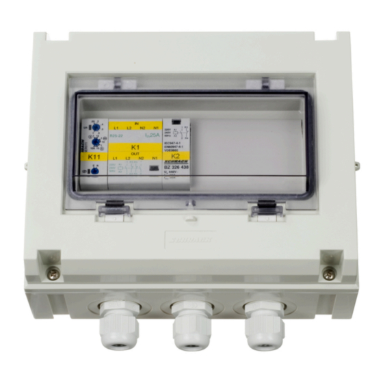
- Page 1 ENGLISH VE Transfer Switch 5kVA, 10kVA Rev 00 - 12/2022 This manual is also available in HTML5.
-
Page 2: Table Of Contents
VE Transfer Switch Table of Contents 1. Introduction ........................... 1 2. Operation ..........................2 3. Installation ..........................3 4. Technical specifications ......................5 5. Electrical diagram ........................6 6. Dimensions ..........................7... -
Page 3: Introduction
It has two inputs and one output and automatically transfers the available AC power from one of the inputs to the output. It can be used with any Victron Energy inverter, providing the inverter power rating does not exceed the transfer switch power rating. -
Page 4: Operation
VE Transfer Switch 2. Operation The transfer switch is situated between a generator or shore power and the inverter. If the voltage level or the frequency of the generator or the shore power varies on input 1, the transfer switch will switch to the inverter on input 2. -
Page 5: Installation
VE Transfer Switch 3. Installation WARNING: Make sure that all AC power sources are switched off or disconnected before and during installation. Mounting: • Install the transfer switch in a dry and well-ventilated area. • To gain access to the transfer switch, remove the four screws in the front panel. •... - Page 6 VE Transfer Switch Connection diagram Digital Multi Control panel. Fusing, earth leakage protection and grounding: • The AC input and output wiring must be protected by fuses or miniature circuit breakers (MCBs) that are suitable for the system's wire cross-section. •...
-
Page 7: Technical Specifications
VE Transfer Switch 4. Technical specifications VE Transfer Switch 5kVA (COS 0) 10kVA (COS 0) Nominal voltage 200 - 250Vac, single-phase Nominal frequency 50 – 60Hz Nominal current input 1 Nominal current input 2 Nominal output current Maximum electromotor (air-conditioner) power 1.3kW Power consumption input 1 Power consumption input 2... -
Page 8: Electrical Diagram
VE Transfer Switch 5. Electrical diagram VE Transfer Switch 5KVA VE Transfer Switch 10KVA Page 6 Electrical diagram... -
Page 9: Dimensions
VE Transfer Switch 6. Dimensions VE Transfer Switch 5kVA VE transfer Switch 10kVA Page 7 Dimensions...
Need help?
Do you have a question about the VE 10kVA and is the answer not in the manual?
Questions and answers