
Related Manuals for Trerice 91400


Summarization of Contents
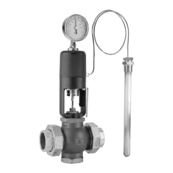
Principles of Operation and Unit Identification
Identifying Your Unit
How to identify Series 91000 and 91400 actuators, including range codes.
Standard Ranges for 91600 Actuators
Recommended working spans for 91600 Safety-Type actuators by range code.
Pressure and Temperature Limits
Maximum Static Pressure Ratings
Static pressure ratings for valve bodies based on size (1/2" to 6").
Maximum Pressure Drop
Maximum permissible pressure drop across the valve for different models and valve types.
Maximum Valve Body Temperatures
Process fluid temperature limits for two-way and three-way valve bodies.
Sensing Bulb Pressure Limits
Pressure limits for sensing bulbs and recommended thermowell usage.
Installation Procedures
Regulator Location Selection
Guidelines for choosing an optimal and accessible installation location for the regulator.
Regulator Installation Steps
Instructions for installing the regulator, including strainer and bypass piping.
Indicator Positioning
How to adjust and tilt the integral dial thermometer for best readability.
Sensing Bulb Information
Sensing Bulb Location
Importance of sensing bulb placement for accurate temperature sensing in various systems.
Sensing Bulb Installation
Detailed steps for installing sensing bulbs into thermowells or process piping.
Operation and Control Point Setting
Placing into Operation
Procedure for initial startup, setting the control point, and system equilibrium.
Routine Service and Maintenance
Stem Cleaning and Lubrication
Maintaining the valve stem for free movement and accurate regulation through cleaning.
Packing Seal Adjustment
Guidance on the self-adjusting packing seal; do not overtighten packing nut.
Stem Seal Packing Replacement
Replacing Valve Stem Packing
Step-by-step guide for removing, cleaning, and installing new stem packing.
Checking Regulator Operation
Inspecting the Actuator
How to check the actuator's thermal system and stem movement for proper function.
Inspecting Valve Body Assembly
Steps to check the valve body assembly for jamming or proper movement.
Valve Body Assembly Procedures
Removing Valve Body Assembly
Detailed instructions for safely disconnecting the valve body from the actuator.
Replacing Valve Body Assembly
Instructions for reassembling the valve body to the actuator, including locknut settings.
Reversing Valve Action
1/2" to 2" Valve Sizes
Specific procedure for reversing the action (heating/cooling) on 1/2" to 2" valve sizes.
Procedure Details
Comprehensive steps for reversing valve action, including stem and plug reassembly.
3-Way Regulators
Mixing and Diverting Applications
Installation and maintenance for 3-way regulators used in mixing or diverting flow control.
Model 91600 Safety-Type
Factory Service and Special Instructions
Guidance on factory service and specific instructions for Model 91600, including stem and protection.
Typical Applications
Heat Exchanger (2-Way Valve)
Example application of a Series 91000 2-way valve in a heat exchanger.
Heat Exchanger (3-Way Diverting)
Example application of a Series 91000 3-way diverting valve in a heat exchanger.
3-Way Mixing Valve Plumbing
Typical plumbing setup for a Series 91000 3-way mixing valve.
Heating Application (Vessel/Tank)
Application example of a heating regulator with sensor in a vessel or tank.
Heat Exchanger Application (Piping)
Application example of a heat exchanger regulator with sensor in piping.
Plating or Pickling Application
Example application of a regulator for plating or pickling baths.
Troubleshooting Guide
Erratic Control Issues
Common causes and corrections for erratic temperature control in regulators.
Temperature Exceeds Control Point
Causes and solutions when the controlled temperature is higher than the desired set point.
Temperature Below Control Point
Causes and solutions when the controlled temperature is lower than the desired set point.
Need help?
Do you have a question about the 91400 and is the answer not in the manual?
Questions and answers