Advertisement
Table of Contents
- 1 Table of Contents
- 2 Disassembly
- 3 Cabinet (Rear) Assy
- 4 Main Board
- 5 Mechanism Deck
- 6 Cassette Lid Sub Assy
- 7 Display Board
- 8 Mechanical Adjustments
- 9 Electrical Adjustments
- 10 Exploded Views
- 11 Cassette Lid Section
- 12 Cabinet Section
- 13 Mechanism Deck Section
- 14 Electrical Parts List
- Download this manual
WM-EX402/EX404/EX405/EX406
SERVICE MANUAL
SPECIFICATIONS
Tape section
Frequency response (Dolby NR off)
Playback: 40 - 14,000 Hz
Headphones 2 jack
Output
Load impedance 8 - 300 ohms
General
Power requirements
3 V
Two R6 (size AA) batteries
(negative ground)
Approx. 115.5 × 83.5 × 32.5 mm
Dimensions (w/h/d)
× 3
(4
5/8
projecting parts and controls
Mass
Approx. 135 g (4.8 oz) / Approx.
215 g (7.6 oz) incl. batteries and
a cassette
Supplied accessories
Stereo headphones or Stereo
earphones with remote
control (1) (EX406 only)
Stereo headphones or Stereo
earphones (1) (EX402/EX404/
EX405 only)
Belt clip (1)
Design and specifications are subject to change without
notice.
MICROFILM
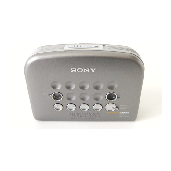
Photo : WM-EX404
× 1
inches) incl.
3/8
5/16
Model Name Using Similar Mechanism
Tape Transport Mechanism Type
Dolby noise reduction manufactured under license from Dolby Labo-
ratories Licensing Corporation.
"DOLBY" and the double-D symbol a are trademarks of Dolby
Laboratories Licensing Corporation.
Notes on Chip Component Replacement
• Never reuse a disconnected chip component.
• Notice that the minus side of a tantalum capacitor may be dam-
aged by heat.
Flexible Circuit Board Repairing
• Keep the temperature of the soldering iron around 270˚C during
repairing.
• Do not touch the soldering iron on the same conductor of the
circuit board (within 3 times).
• Be careful not to apply force on the conductor when soldering
or unsoldering.
– 1 –
AEP Model
E Model
NEW
MF-WMFX483-147
CASSETTE PLAYER
Advertisement
Table of Contents

Related Manuals for Sony Walkman WM-EX405


Summarization of Contents
Specifications
Tape Section
Details playback frequency response and output load impedance.
General Specifications
Covers power requirements, dimensions, mass, and supplied accessories.
Important Service Notes
Notes on Chip Component Replacement
Guidelines for replacing chip components, including warnings about tantalum capacitors.
Flexible Circuit Board Repairing
Recommendations for soldering on flexible circuit boards, covering temperature and handling.
Section 2 Disassembly
2-1. Cabinet (Rear) Assy
Procedure for disassembling the rear cabinet assembly, including screw removal and lid case opening.
2-2. Main Board
Procedure for disassembling the main board, including serrated IB lock and flexible boards.
2-3. Mechanism Deck
Procedure for removing the mechanism deck from the front cabinet assembly.
2-4. Cassette Lid Sub Assy
Procedure for installing the cassette lid sub assembly, including spring and clips.
2-5. Display Board
Procedure for disassembling the display board and removing clips.
Section 3 Mechanical Adjustments
Torque Measurement
Details torque meter readings for FWD, REV, and FF/REW modes.
Section 4 Electrical Adjustments
Tape Speed Adjustment Procedure
Outlines the procedure for adjusting tape speed using a frequency counter.
IC Block Diagrams
IC301 LA4585M-TLM
Diagram showing the internal block structure of IC301.
IC302 NJM2185AV-TE2
Diagram showing the internal block structure of IC302.
IC601 MM1370XVBE
Diagram showing the internal block structure of IC601.
IC701 TMP47C243LM-FV81CS
Diagram showing the internal block structure of IC701.
Section 6 Exploded Views
6-1. Cassette Lid Section
Exploded view and parts list for the cassette lid assembly.
6-2. Cabinet Section
Exploded view and parts list for the cabinet assemblies.
6-3. Mechanism Deck Section
Exploded view and parts list for the mechanism deck components.
Section 7 Electrical Parts List
Display Board Components
List of electrical components for the display board.
Main Board Components
List of electrical components for the main board.
Other Board Components
List of electrical components for various other boards.
Need help?
Do you have a question about the Walkman WM-EX405 and is the answer not in the manual?
Questions and answers