Table of Contents
Advertisement
Quick Links
P R E L I M I N A R Y
GE Healthcare
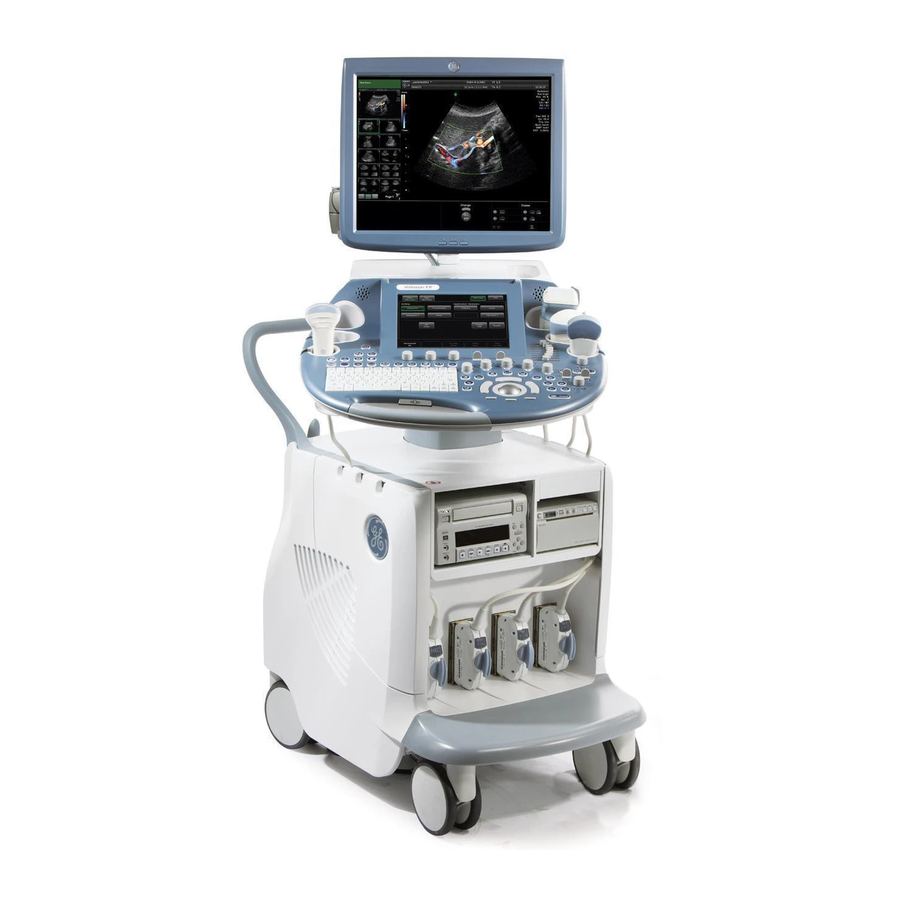
Voluson E-Series BT15 / BT16 / BT17 / BT18
Service Manual
English (English)
•
Voluson E6 / Voluson E8 / Voluson E10 with Software version EC300, 15.x.x (BT15)
•
Voluson E6 / Voluson E8 / Voluson E10 with Software version EC310, 16.x.x (BT16)
•
Voluson E6 / Voluson E8 / Voluson E10 with Software version EC320, 17.x.x (BT17)
•
Voluson E6 / Voluson E8 / Voluson E10 with Software version EC330, 18.x.x (BT18)
(NOVEMBER 4, 2013)
VE6_VE8_COVER.FM
Document Number: 5539550APB
Revision 6
© 2014 - 2017 by General Electric
0123
Advertisement
Table of Contents
Troubleshooting

Related Manuals for GE BT17


Summarization of Contents
Introduction
Important Precautions
Essential safety guidelines and warnings for operating personnel before installation or servicing.
Legal Notes
Publication copyright, revision policy, and trademark information.
Purpose of this Service Manual
Details the scope and content of the service manual, covering 10 chapters.
Important Conventions
Explains manual conventions, model designations, icons, and safety precaution messages.
Safety Considerations
Covers human, mechanical, electrical, and auxiliary device safety precautions.
EMC, EMI and ESD
Information on Electromagnetic Compatibility, Interference, and Electrostatic Discharge prevention.
Customer Assistance
Provides contact information for technical support and system manufacturer details.
Site Preparation
General Requirements
Details environmental, electrical, and EMI requirements for system installation.
Facility Needs
Outlines purchaser responsibilities and required facility features for installation.
Setup Instructions
Setup Reminders
Provides average installation time, warnings, and lifting guidelines.
Receiving and Unpacking the System
Instructions for inspecting the shipping cardboard and unpacking the system.
Preparing for Setup
Checklist for verifying customer order and inspecting system components.
Completing the Setup
Procedures for connecting power, powering on, and booting the system.
Connection of Auxiliary Devices
Guides for connecting various peripherals like monitors, printers, and modems.
Printer Installation
Steps for installing and configuring B/W, Color, DeskJet, and Network Laser printers.
System Configuration
Details on configuring system settings across various categories like General, Connectivity, and Backup.
On-board optional Peripherals
Lists approved peripherals and accessories compatible with the system.
External I/O Connectors
Details on external I/O connectors, pin outs, and identification of UI components.
Available Probes
Reference for part numbers of available probes for new or replacement service.
Software/Option Configuration
Guidance on configuring software options and referring to the Basic User Manual.
Connectivity Setup
Describes system connectivity options including network and DICOM configurations.
Network Configuration
Covers TCP/IP, Wireless Network, Cellular Modem, and E-mail setup procedures.
Connectivity Setup Worksheet
Provides a worksheet to record site system and network information for setup.
Paperwork
Information on documentation and product locater installation cards.
Functional Checks
Required Equipments
Lists necessary items for functional checks, including media and probes.
General Procedure
Safety precautions and lockout/tagout requirements for performing checks.
Functional Checks
Basic checks of system modes, measurements, and options; refer to Basic User Manual.
Backup and Restore Database, Preset Configurations and Images
Procedures for backing up and restoring system configurations and image archives.
Software Configuration Checks
Steps to verify system settings for General, Administration, Connectivity, Backup, etc.
Peripheral Checks
Verifies the proper functioning of peripherals like printers and ECG.
Mechanical Function Checks
Checks mechanical functions such as control console positioning and brakes.
Site Log
A table for documenting site-specific information related to service.
Components and Functions (Theory)
General information
Overview of the Voluson E-Series system, modes, and major components.
FrontEnd Processor
Details the RTF, RSE, RFM, and RSX boards within the FrontEnd processor.
BackEnd Processor
Describes the PC-Motherboard, HDD, Graphic Card, RTV, and RTB components.
Internal I/O
Details internal I/O configurations based on PC motherboard and BT-version.
Control Console (User Interface)
Explains the electronic sub-assemblies and components of the user interface.
Monitor
Provides details on monitor adjustment and settings.
External I/O
Details external I/O connectors on the system and monitor.
Peripherals
Lists and describes recording tools, printers, and DVD drives.
Power Distribution
Explains the RSP Power Supply Module, its mechanical concept, and voltage ranges.
Mechanical Descriptions
Provides physical dimensions and control console positioning details.
Air Flow Control
Describes the system's air flow distribution and cooling mechanisms.
Service Platform
Information on InSite connectivity, access, and security levels.
Common Service Desktop (CSD)
Details accessing the CSD for service tasks and its internationalization.
Service Page
Describes access and security for the service page and its tools.
Boot Screen Functions
Explains functions available on the boot screen like Voluson, GE-Service, Rollback, and Memtest.
Service Adjustments
Regulatory
Ensures compliance with national regulatory information and tests.
LCD Monitor Adjustment
Guides for adjusting monitor tilt, rotation, height, and locking mechanisms.
Control Console Positioning
Instructions for adjusting control console rotation, translation, and height.
Modification of Keyboard Layout
Procedure for changing keyboard layout for different languages.
Diagnostics/Troubleshooting
Collect vital System Information
Procedure to gather system type, serial number, software version, and backup details.
Request for Service (RFS)
Steps to contact GE for service requests via the InSite link or Service page.
Check Point Voltages
Explains status LEDs for User Interface and Power Supply (RSP).
Screen Captures and Logs
Procedures for capturing screens and exporting system data and logs.
Remote Access to the Service Platform
Information on remote access capabilities using VCO and Disruptive Mode.
Common Service Desktop (CSD)
Details on accessing and navigating the Common Service Desktop interface.
How to use the Auto Tester program
Step-by-step guide to activate and use the Auto Tester program for recording processes.
Troubleshooting Trees, Instructions and Tech Tips
Diagnostic flowcharts and tips for common system issues.
Replacement Procedures
Returning/Shipping System, Probes and Repair Parts
Guidelines for returning or shipping system components, ensuring cleanliness and proper packaging.
System Software - Installation/Upgrade procedure
Describes methods for system software updates via DVD or InSite connection.
Software and Functional Checks after Installation/Upgrade procedure
Verifies correct settings and performs functional checks post-installation or upgrade.
Image Settings Only - Loading Procedure
Procedure for loading image settings such as presets and scan assistant configurations.
Full Backup (Full System Configuration) - Loading Procedure
Procedure for loading a full system configuration backup.
Image Archive - Loading Procedure
Procedure for loading a backup of the image archive containing patient data and images.
Replacement or Activation of Options
Explains how to activate software options using Demo or Permanent Keys.
Replacement of Covers
Procedures for replacing footrest, front frame, and air filter covers.
Replacement of the Cable Holder
Procedure for removing and installing the cable holder.
Replacement of the Probe Holder (Kit)
Procedure for replacing the probe holder kit.
Replacement of the Probe Holder for Endocavity probes
Procedure for replacing the probe holder for endocavity probes.
Replacement of the Trackball Ring
Procedure for removing and mounting the trackball ring.
Replacement of Key Caps (by special native language keys)
Procedure for replacing keyboard key caps with special native language keys.
Replacement of the Caps for Encoders and/or Joycoders
Procedure for replacing caps on encoders and joycoders.
Replacement of the Caps for Hardkeys
Procedure for replacing circle key caps on the keyboard.
Replacement of Fuses at Power Supply Module (RSP)
Procedure for replacing fuses located in the Power Supply Module (RSP).
Replacing optional Peripherals / How to mount Peripherals at a later date
Guidelines for mounting or replacing optional peripherals like secondary monitors.
Renewal Parts
List of Abbreviations
Alphabetical list of abbreviations used in the manual.
Parts List Groups
Categorizes mechanical and user-accessible parts for the console.
Housing - Mechanical Hardware Parts & Covers
Lists mechanical hardware parts and covers for the system housing.
User Interface
Lists parts related to the console, keyboard, display, and speakers.
Monitor + Monitor Replacement Parts
Lists replacement parts for OLED and LCD monitors, including monitor arms.
Main Power Modules
Details main power modules, including the Power Supply (RSP) and fuse sets.
Main Board Module
Lists components for FrontEnd and BackEnd PC parts.
Options and Upgrades
Catalog of software options, upgrades, and system/boot DVDs.
Miscellaneous Cables
Lists various miscellaneous cables used in the system.
Optional Peripherals and Accessories
Lists optional peripherals like printers, drives, scanners, and modems.
System Manuals
Provides part numbers for system and user manuals for different models.
Probes
Lists and describes various types of 2D, 4D, and CW probes available.
Biopsy Needle Guides
Lists biopsy needle guides and associated probes.
Care and Maintenance
Why do Maintenance
Explains the importance of maintenance, record keeping, and quality assurance.
Maintenance Task Schedule
Outlines recommended care and maintenance tasks and their frequencies.
Tools required
Lists special tools, supplies, and equipment needed for maintenance.
System Maintenance
Covers preliminary and functional checks of the ultrasound system.
Using a Phantom
Notes on using a phantom for Quality Assurance Program tests.
Electrical Safety Tests
Details electrical safety tests including leakage current limits and procedures.
When there's too much Leakage Current...
Troubleshooting steps for excessive leakage current issues.
Ultrasound Equipment Quality Check
Guidance to contact GE Service Representative for quality checks.
Need help?
Do you have a question about the BT17 and is the answer not in the manual?
Questions and answers