Table of Contents
Advertisement
Quick Links
Advertisement
Table of Contents

Related Manuals for SK PSP 21


Summary of Contents for SK PSP 21
- Page 1 PNEUMATIC PRESSES SERIES PSP_PST_ 21/29/42/55 OPERATION AND MAINTENANCE MANUAL Škrlj d.o.o., tel.: ++386 (0)5 36 43 500 – fax: ++386 (0)5 36 43 525 www.sk-group.biz - sk@sk-group.biz mati na št.: 5559839 – dav na št.: 94136408 NAV_PSL_ 2008/07_UK_v4...
-
Page 2: Table Of Contents
TABLE OF CONTENTS: INTRODUCTION ........................... 4 PURPOSE OF PNEUMATIC PRESS .................... 4 GUARANTEE ..........................4 HEALTH AND SAFETY ......................... 5 Meaning of the symbols....................... 5 GENERAL SAFETY PRECAUTIONS ..................5 SAFETY DEVICES......................... 6 4.3.1 Emergency STOP button....................6 4.3.2 Safety cord ........................7 4.3.3 Protection against overpressure in the drum .............. - Page 3 Discharging the press ......................33 CLEANING OF THE PRESS....................34 10.1 Cleaning of the drum interior..................... 34 10.2 Cleaning the drain channels (PST models) ..............35 10.2.1 The draining channel dismounting procedure: ............... 35 10.2.2 Reassembly of the draining channels ................36 10.3 Cleaning the drain channels without removing them (optional for PST models)..
-
Page 4: Introduction
1 INTRODUCTION We thank you for your trust, which you demonstrated by purchasing our pneumatic press. In order for it to be used successfully and for a long period we ask you to follow the instructions and warnings for a safe and proper use. The instructions are intended for the operator and they should always be kept at hand. -
Page 5: Health And Safety
4 HEALTH AND SAFETY 4.1 Meaning of the symbols In the instructions following symbols are used to warn the user against danger or special attention: Symbol Designation Meaning DANGER Danger because of the electric current! DANGER Danger because of the moving parts of the machine! WARNING General instruction, recommendation, forbiddance…! IMPORTANT INFORMATION... -
Page 6: Safety Devices
Once a year, the screws that connect the membrane to the drum frame must be tightened. Before that, disconnect the press from the mains supply. The hatch should be open and protected against inadvertent closing. When filling with the pump, be careful not to exceed the limit pressure value in the drum. You must stop the pump as soon as you hear the acoustic signal, in order to reduce the pressure. -
Page 7: Safety Cord
4.3.2 Safety cord The space between the drum and the press frame is protected by a red safety cord. Any significant vibration or pulling on the cord triggers a micro switch, which in turn immediately stops the press. Always check the safety cord tension and position prior to operating the press. If the safety cord is not installed or its tension is incorrect, the press will not function. -
Page 8: Protection Against Overpressure In The Drum
4.3.3 Protection against overpressure in the drum Following safety systems are used: Maximum pressure that can be achieved with the compressor is limited to 1.5 bar (by some executions maximum pressure is 1.8 bar). In a case the pressure is exceeded (e.g. due to a valve fault), the vacuum pump valve and the safety valve automatically open at 2.0 bar, to release air from the drum and to decrease the pressure to the allowed level. -
Page 9: Press Transport And Setting Up
5 PRESS TRANSPORT AND SETTING UP 5.1 Transport of the press Transportation, unloading and lifting may only be done by skilled personnel. The manufacturer shall not be kept liable for any personal injuries or material damages resulting from disregarding safety regulations applicable to the transportation, unloading, lifting… During lifting and manipulating the press, no person shall move or stay below the hoisted load or within the operating range of the crane. -
Page 10: Mounting And Storage Of The Press
5.2 Mounting and storage of the press Pneumatic press is delivered wrapped in foil. The foil must be removed immediately after delivery. Otherwise, effects of weather factors (exposure to strong sun radiation etc.) may hinder complete and neat removal of the foil. Place the press into a dry and vented space on a level floor. -
Page 11: Switching On The Press
6 SWITCHING ON THE PRESS 6.1 Electrical connection The electrical connection of the press must be carried out by skilled personnel (electrician)! Electrical connections (including earth lead and protection) should be performed in accordance with applicable standards. Electrical diagrams are attached to the manual! Connect the press to a three phase 400 V 50/60 Hz mains supply. -
Page 12: Rotating Direction Of The Drum
Step 3: Check the mains supply voltage indicated on the identification sticker (on the leg of the press) and on the yellow sticker under the connecting terminals. Sticker with mains supply voltage The identification tag is positioned on the support behind the box Step 4: Insert the cable into the sleeve on the electric... -
Page 13: General Data
7 GENERAL DATA 7.1 Technical data (dimensions and capacity) Pneumatic presses, L series open drum, semi-membrane, half of the drum perforated Drum design enclosed drum, semi-membrane, draining channel Designation PSP 21 PST 21 PSP 29 PST 29 PSP 42 PST 42... -
Page 14: Press Orientation
PSP/PST_ 42, 55 7.2 Press orientation Back side of the press is the side with the the central filling connector Front side of the press is the side where the drive module of the maschine is situated. When checking drum rotation, note that it is always regarded from the front. The drum must rotate in the same direction as the arrow on the key. -
Page 15: Pneumatic Press Operation
7.3 Pneumatic press operation Pneumatic press is a technical-oenological process tool designed for controlled pressing of grapes. It allows the wine-maker to actively intervene in the processes in the course of pressing, to continually adjust and govern the processes. Soft pressing of grapes or lees by means of a membrane and compressed air prevents mechanical damaging of grapes (less damage to the hard parts of grapes) and in turn minimises the leaching of undesired ingredients. -
Page 16: Description Of The Pneumatic Press
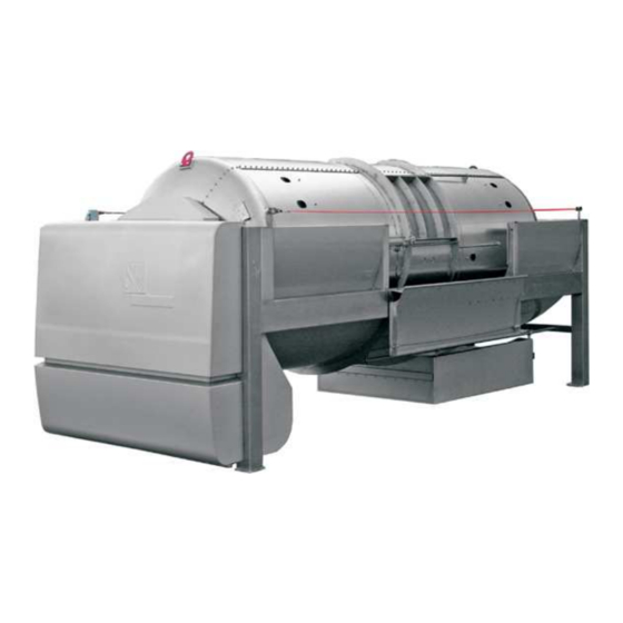
8 DESCRIPTION OF THE PNEUMATIC PRESS 8.1 Components Key press components. The equipment can differ for various press types and sizes. Double sliding Press drum hatch The front Red safety cord cover with the drive module AVk controller Central filling connection Juice collection NAV_PSL_ 2008/07_UK_v4... -
Page 17: Built-In Components
8.2 Built-in components Under the front cover is the drive module of the press. When you open the front cover of the press, MAKE SURE that the hydraulic struts fix the cover in the upper position. Pneumatic presses PS_21, 29 and 42: Service command vacuum pump safety valve... -
Page 18: Materials
Upon activating the press, check the rotating direction of the drum. Operation with the improper rotation direction is not allowable and could damage the compressor (for detailed instructions, see chapter 6.2 Drum rotation direction). The presses that have hermetic hatches or any other form of pneumatic drive (hatch, pan etc.) have an auxiliary compressor built in. - Page 19 Perforated double sliding hatch for perforated drum presses Double sliding hatches for closed drum presses with drain (PSP) channels (PST) Manual opening of the hatch: Opening the hatch in the upper position requires some strength. Therefore, use the opening lever, which is included with the press. Rotate the drum so that the hatch stops in a position that is suitable for opening.
-
Page 20: Double Hatch With Pneumatic Drive (Optional)
8.4.2 Double hatch with pneumatic drive (optional) Pneumatic cylinder Sliding hatch The pneumatic drive is particularly useful for large presses, as it makes closing and opening the hatch much easier. The drive can be installed on one or both hatches, and is controlled in manual mode (M) with the following two keys: key to open the hatch key to close the hatch... -
Page 21: Hermetic Hatch With Manual Opening/Closing (Optional For Pst)
8.4.3 Hermetic hatch with manual opening/closing (optional for PST) Sealing tube for the hermetic hatch Hermetic hatch cover Hatch dimensions: 485 x 600 mm The cover of the hatch is opened/closed manually. The state of the sealing tube is regulated using a valve on the outer edge of the hatch frame. Valve closing device The seal is inflated or deflated, according to the position the valve is in. -
Page 22: Hermetic Hatch With Pneumatic Drive (Optional For Pst)
8.4.4 Hermetic hatch with pneumatic drive (optional for PST) Pneumatic cylinder Hermetic hatch cover Sealing tube for the hermetic hatch For hermetic hatches with pneumatic drive, the movement (opening and closing) is controlled by two keys on the control panel. key to open the hatch key to close the hatch The position and movement of hatches is controlled by two... -
Page 23: Press Drum
8.5 Press drum The press drum is constructed according to pressure vessel guidelines (PED 97/23/EG). The horizontal shape of the drum, combining large length and small diameter, allows faster outflow of juice, which results in less sediment in the must. On the inside, the drum is lined with an impermeable membrane shaped to cover half of the drum surface. -
Page 24: Juice Collection Pan
8.6 Juice collection pan 8.6.1 Small pan on guides (optional on PS_21 and PS_29) Juice collection pan volume 100 l The pan is square and attached on the same side as the central filling. You can rotate the pan so that the outlet is on any side of the press. -
Page 25: Large Pan On Wheels (Optional On Ps_21 And Ps_29)
8.6.2 Large pan on wheels (optional on PS_21 and PS_29) Large must collector pan on wheels. Optional on PS_21 and PS_29 presses. Underneath the drum, there is a plateau on either side of the press, guiding the must to the pan. Juice pan volume: pneumatic press PS_21 600 litre... -
Page 26: Control Box
8.7 Control box The AVk automatics control panel is connected to the press via a cable and connector. This allows mounting in different locations on the press itself or separate installation. For transport, the control panel is fixed, with two screws, on the press frame under the front lifting cover. -
Page 27: Level Switch In The Collection Pan
8.8.2 Level switch in the collection pan The level switch is designed to control the operation of the pump which transfers must from the collection pan to the container during the pressing. The collection pan is fitted with two floats on a special metal bracket. -
Page 28: Equipment For Macaration (Only Models Pst)
8.8.3 Equipment for macaration (only models PST) The hermetic hatch combined with the plugging of drain channel outlets, allow lees maceration and its agitation by means of the press drum rotation. Hermetic hatch with pneumatic draining channel opening draining channel plug opening/closing To perform maceration, follow these instructions: Before filling the press, rotate the drum to bring the hatch to its top position. -
Page 29: Operating The Press
9 OPERATING THE PRESS The press is designed for pressing grapes and dregs. The use for any other purpose without the approval from the manufacturer is prohibited. 9.1 Before use Prior to the first startup of the press, carefully examine the instructions for safe operation and maintenance of the pneumatic press, and always observe these instructions. -
Page 30: Filling The Press Through The Central Filling Connector
9.2.2 Filling the press through the central filling connector Central filling valve: The central filling connector is standard with all presses. The shaft opening is size DN 100. Central filling opening / inside The flange on the outer side allows for installation of DN65, DN80 or DN100 valves. - Page 31 Pneumatic valve for central filling connector (option): The pneumatic valve is being regulated using the key on the control panel in manual mode (M). Use this key: open/close central filling valve For additional information regardin use and functioning of the pneumatic valve, see the second part of this manual (Automatics AV).
-
Page 32: Selecting The Pressing Program
Before filling: Make sure you removed the plugs from the drain channels (PST models); Make sure that the membrane adheres to the internal walls along the whole surface. This is particularly critical with presses where the central filling system is not fitted with an acoustic warning (siren) for the excessive pressure or press full condition. -
Page 33: Discharging The Press
9.4 Discharging the press After pressing is concluded, empty the press. For presses with manual sliding hatches, follow these instructions: First, switch the press to manual operation (button M) Using the keys, turn the drum so that you can open the hatch. Before opening the hatch, turn off the press. -
Page 34: Cleaning Of The Press
Cleaning of the drum interior The L series presses have a DN80 DIN11851 cleaning opening with a corresponding plug. The cleaning opening allows for easier cleaning of the interior, as during cleaning, the water and the remains flow out of this opening. -
Page 35: Cleaning The Drain Channels (Pst Models)
Disconnect the press from the mains supply and open the drum hatch. If the press has pneumatic hatch drive, first open the hatch and then disconnect the press. Make sure that the hatch is secured against sudden closing. Wash the interior with water, as described at the beginning of this chapter. -
Page 36: Reassembly Of The Draining Channels
Step 3: Remove the drain channels and carefully remove it from the drum. Make sure not to damage the membrane. In the same way, remove the joining piece. Step 4: Remove the draining channel plugs on the drum exterior. Step 5: Following this procedure, remove all drain channels and remove them from the drum. -
Page 37: Cleaning The Drain Channels Without Removing Them (Optional For Pst Models)
10.3 Cleaning the drain channels without removing them (optional for PST models) 10.3.1 Channel cleaning hose (length: 3 m). The drain channels can be cleaned without removing them by using a special hose. The procedure is quick and simple. Attach the hose to a high-pressure cleaner. Insert the bayonet into the cleaner handle and rotate it 90°... -
Page 38: Maintenance
11 MAINTENANCE Before performing any maintenance, disconnect the press from electricity. 11.1 Removing humidity from the space between the drum and the membrane On the external side of the drum, an outlet for removing the humidity from the space between the drum and the membrane is located. -
Page 39: Membrane
Step 2: Unscrew the chain tension adjustment screw counter nut. Step 3: Adjust the chain tension with the screw. Move the screw to achieve proper chain slackness. The chain slackness should be 10 -15 mm (5 mm up, 5 mm down). chain adjustment screw Step 4:... -
Page 40: Maintenance Of The Compressor
Instruction for membrane patching If the membrane is damaged or torn, minor repairs can be performed by patching the damaged surface with the same material. Patches can be ordered from your local distributor. When repairing the membrane, please observe the following procedure: 1. -
Page 41: Care And Maintenence Of Stainless Steel Eqipment
11.7 Care and maintenence of stainless steel eqipment When you operate with the press, be careful that you do not damage the surface of the stainless steel. We recommend that you protect the stainless surfaces from mechanical damage (scratches, strokes,…), damaging influence of chemical matters (especially chlorine based matters) and contacts with materials which are not stainless. - Page 42 The cleaning procedures for stainless steel products If the stainless steel products are very dirty and “colouring” caused by negligence or wrong treatment with the product is present, alternative methods such as the following have to be used: type of dirt cleaning methods notes recommendations...
-
Page 43: Spare Parts
11.8 Spare parts Spare parts are available on request from the manufacturer. They may be ordered directly from the manufacturer or through his representative. Any repair or replacement of the damaged parts may only be performed by an authorized person – serviceman. In case of intervention by an unauthorized serviceman, the guarantee becomes void and the unprofessionally done repairs may cause danger to the operator using the machine. - Page 44 Test for locating the error. Drum hatch has to be closed, the press switched on. Error/Problem Possible cause Recommended precaution Switch on the internal service Fuse F3 switched off. Check F3 fuse. commands and P– Active thermo protection in Wait for 5 minutes for motor to vacuuming.
- Page 45 The manometer on control Problems with connection tube. Check the placement and panel does not work. connection of the tube. The siren switched on. High pressure on entry in the STOP the charging trough axial drum. feeding. NAV_PSL_ 2008/07_UK_v4...
Need help?
Do you have a question about the PSP 21 and is the answer not in the manual?
Questions and answers