
Related Manuals for Rogers KIV Series


Summary of Contents for Rogers KIV Series
- Page 1 ® Rotary Screw Air Compressors Model #: __________________ Serial #: __________________...
- Page 2 WARNING SUMMARY Read and understand the contents of this manual and the Operation, Display and Controls Manuals for your compressor before installing, operating, or maintaining the compressor. Failure to follow these instructions may result in serious injury or death. Electricity and compressed air are dangerous. Whenever performing maintenance or compressor service work, ensure all electrical supply power is disconnected and mechanically locked out.
- Page 3 WARNING SUMMARY – Continued. Never assume it is safe to work on your compressor because it is not operating. Many systems have automatic start/stop controls, which means the compressor may start at any time. Failure to comply with these instructions may result in serious injury or death. Facility personnel using the compressor equipment must thoroughly read, understand and comply with all posted WARNING, CAUTION and DANGER placards placed on the K Series compressor system.
- Page 4 PREFACE AND MANUAL OVERVIEW Rogers KI and KIV Series rotary screw air compressors are designed for efficiency and longevity. Their professional engineering, rugged design and quality construction will provide many years of trouble-free operation if proper temperatures and lubrication are maintained.
-
Page 5: Table Of Contents
1.5.3 Separator Element 25 to 100 HP ............ Page 7 Description of Standard Capacity Control System ........Page 7 1.6.1 KI Series (10-50 HP) Load/Unload ..........Page 8 1.6.2 KIV Series (10-100 HP) VFD and Load/Unload ........ Page 8 1.6.3 Standby Delay Timer ............... - Page 6 CHAPTER 4 – COMPRESSOR LUBRICATION COMPRESSOR LUBRICANT General ....................... Page 22 Lubricant Service Intervals ................. Page 22 Lubricant Level Check ................Page 22 Lubricant System / Cooling Data ..............Page 23 Special maintenance of Compressor Lubricant System ......Page 23 4.5.1 Deposits ..................
- Page 7 KI and KIV Series Rotary Screw Air Compressor Start-Up Report ......Electrical Schematic – KI Series 10 HP: 208, 230, 460 VAC ........Electrical Schematic – KI Series 15 Through 50 HP: 208, 230, 460 VAC ....Electrical Schematic – KI Series 60 Through 100 HP: 460 VAC ......
- Page 8 INTENTIONALLY BLANK...
-
Page 9: Chapter 1 - General Information
CHAPTER 1 GENERAL INFORMATION... -
Page 10: General
Maximum pressure capability is generally limited by compressor drive motor horsepower. The Rogers KIV Series air compressors are virtually identical to the KI Series except the primary control flow control is accomplished by motor speed control through a VFD (Variable Frequency Drive). The compressor and motor speed up and slow down within a range to adjust its output to match demands. -
Page 11: Description Of Air Flow
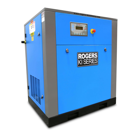
Figure 1. KI and KIV Compressor Identification (Typical). Description of Air Flow This manual covers several different models. Figures 2 and 3 show a conceptual representation of component layout within the compressor package and may not depict a component’s exact location. With the motor running and compressor operating, under loaded conditions, low pressure (slight vacuum) is achieved at the compressor inlet. - Page 12 Figure 2. KI/KIV 10 through 20 Horsepower Air Flow Diagram. Table 1. KI/KIV 10 through 20 Horsepower Air Flow Components. ITEM DESCRIPTION Oil Cooler Oil Filter Head and Temperature Control Valve Oil Filter Element Intake Air Filter (Ambient Air) Drive Shaft Oil Drain Valve ASME Safety Relief Valve Oil Level Gauge (Not Shown)
- Page 13 Figure 3. KI/KIV 25 through 100 Horsepower Air Flow Diagram. Table 2. KI/KIV 25 through 100 Air Flow Components. ITEM DESCRIPTION Oil Cooler Oil Filter Head and Temperature Control Valve Oil Filter Element Intake Air Filter (Ambient Air) Inlet Check and Unloading Valve Drive Shaft Oil Drain Valve Oil Level Gauge (Not Shown)
-
Page 14: Description Of Lubricant And Cooling System
Description of Lubricant Flow and Cooling System A diagram of the compressor lubricant system is shown in Figure 2 and 3. When the compressor operates, lubricant from the reservoir of the separator tank is circulated through the lubricant cooler and lubricant filter and injected into the compressor casing by differential pressure. -
Page 15: Air-Cooled Coolers
1.4.2 Air-Cooled Coolers The combination air-cooled lubricant cooler/aftercooler is comprised of two aluminum bar and plate construction heat exchangers. A cooling fan blows cooling air across both coolers to reject heat from both the compressor lubricant and the compressed air. The fan is driven by an independent cooling fan motor. -
Page 16: Description Of Air And Lubricant Separator System
Description of Air and Lubricant Separator System 1.5.1 Air / Lubricant Separator Reservoir The air / lubricant separator reservoir is an ASME coded pressure vessel which serves as a fluid reservoir and provides mechanical separation of the lubricant and air. The air / lubricant reservoir should not be welded on or modified in any way. -
Page 17: Ki Series (10-50 Hp) Load/Unload
Figure 6. Typical Inlet Valve. 1.6.1 KI Series Standard Control, (10 – 100 HP), Load Unload Operation The standard operating mode of the KI 10-100 HP unit is load / unload. The load and unload set points are set in the controller and are adjustable (see Description of Operations / Display and Controls manual). -
Page 18: Maximum Operating Pressure With Standard Motor
All KI and KIV units have a standby delay timer which will shut the compressor off if it has been operating unloaded for a set period of time. The unload timer is adjustable. See Description of Operations / Display and Controls manual to set this timer. Maximum Operating Pressure with Standard Motor CAUTION DO NOT exceed motor nameplate Service Factor amps at 100% capacity. -
Page 19: Chapter 2 - Installation Instructions
CHAPTER 2 INSTALLATION INSTRUCTIONS... -
Page 20: Installation
The motor must not operate at full load for prolonged periods in ambient temperatures greater than 104 °F (40 °C). If ambient temperatures falls below 36 °F (2 °C), consult your Rogers factory representative for recommendations on how to protect the machine from cold conditions. -
Page 21: V-Belt Drive System (10-50 Hp)
Table 1. Compressor Rotation. UNIT DRIVE DIRECTION KI(V) 10 - 30 Belt Clockwise KI(V) 40 and 50 Belt Counter Clockwise KI(V) 60 Direct Counter clockwise KI(V) 75 Direct Clockwise KI(V) 100 Direct Counter clockwise Belt Drive units - Viewed when facing compressor shaft and belt sheave. Direct Drive units –... -
Page 22: V-Belt Alignment
2.5.2 Belt Alignment Examples of poor belt alignment are shown in Figure 2. Figure 2. V-Belt Alignment. a. Drive and driven shafts are not in alignment. b. Driven shaft has angular misalignment. c. Sheave locations are not inline. d. Correct location of sheaves, belts are inline and parallel. 2.5.3 V-Belt Inspection Remove belt guard and inspect belt condition during the 6,000 hour service or whenever conditions... -
Page 23: Cooling
Maintain coolers free of dust, dirt, and foreign debris by choosing a location that minimizes exposure. Ducting from discharge of air cooled coolers and require special design considerations to maintain sufficient air flow for ventilation. Additional assist fan(s) may be necessary. Contact your Rogers factory representative for assistance. -
Page 24: Optional Moisture Separator Drain
Small amounts of lubricant may be present in the condensate and must be disposed of properly. A wet (control) air receiver can also perform the moisture removal function provided the compressed air flows through the receiver. Additional air treatment may be needed for your application to meet the requirements for higher quality air. -
Page 25: Air Receiver
2.12 Air Receiver An auxiliary air receiver is necessary for most applications. Contact your Rogers factory representative for proper sizing of a receiver for your application. Do not connect a rotary screw compressor on the same air line with a reciprocating unit before the air receiver. The pulsating pressure generated by the reciprocating compressor may cause erratic operation of the rotary screw compressor. -
Page 26: Chapter 3 - Electrical Information
CHAPTER 3 ELECTRICAL INFORMATION... -
Page 27: Electrical
ELECTRICAL Starter and Wiring The separator wiring diagram furnished with the starter should be followed. See Description of Operations / Display and Control manual for typical schematics. The control panel is pre-wired and receives control power from terminals on the line side of the motor starter. The control transformer, located in the control panel, is sized for the compressor controls only. -
Page 28: Motor Rotation
4. Main Motor Overloads - the main motor overload can be changed in the menu of the controller. It will be necessary to power the machine back up to make these changes. Power up the machine, but do not start it. See Description of Operations / Display and Control manual for overload setting screen. -
Page 29: General
3.4.1 General Motors of various makes are used on Rogers KI and KIV Series units. Check motor connections for proper voltage at the motor terminals. 3.4.2 Motor Lubrication Refer to motor manufacturer’s operating instructions for lubrication data. Care should be exercised when lubricating. -
Page 30: Compressor Lubricant
CHAPTER 4 COMPRESSOR LUBRICANT... -
Page 31: General
Alternative lubricants may have different change intervals, contact you Rogers factory representative for assistance before changing to alternative lubricants.. The standard factory lubricant fill is Rogers CLS-46. At 1,000 hour intervals, submit a lubricant sample to Rogers factory for analysis. Change lubricant every 6,000 hours for clean environments and operating temperatures below 190 °F (88 °C). -
Page 32: Lubricant System / Cooling Data
Such deposits can interfere with operation of valves, filters and related cooling system equipment. Minor deposits may be removed by flushing the system with an approved cleaning agent. Consult with you Rogers factory representative for recommendations. Completely drain lubricant while hot from every component that contains lubricant: 1. -
Page 33: Long Term Storage
4.5.5 Lubricant Sample Kit A fluid analysis kit containing a sample bottle, labels and instructions are available from Rogers Machinery Company, Inc. Contact the Service Department to request part number CLS46-TESTKIT. Collect a sample from the oil filter element or from the lubricant drain line supplied on the separator tank,... -
Page 34: Lubricant Filter
Provide all the information shown on the left-hand label in Figure 1. Be sure to provide all information of possible hazards related to a given sample. If a noteworthy situation exists, all information shall be clearly marked on the sample bottle label. Tightly close the bottle and attach the information label on the side of the bottle. -
Page 35: Lubricant Filter Change Intervals
Separator Element Replacement 4.7.1 Spin-On Style, 10 – 20 HP NOTE Each lubricant separator element is of one piece construction. Due to the nature of the unit it is not cleanable. Care should be taken in handling the element to avoid damage. Replace the lubricant separator elements after every 3,000 hours of operation. - Page 36 Figure 3. KI Top Hat Style Separator / Reservoir. WARNING A potential fire hazard exists if static electricity is allowed to build on the separator tank element. The staples are used to ground the separator element to the separator tank and prevent the buildup of static electricity.
-
Page 37: Lubricant Scavenging System
3. Disconnect pressure transmitter and high temperature switch. Remove lubricant and scavenging line (steel tubes) from the fittings at the top of the reservoir cover plate. Disconnect air discharge plumbing at check valve. Carefully remove, deflect and tie the free ends of all remaining tubing away from reservoir flange without causing permanent set or deformation. - Page 38 Lubricant from inside the lubricant separator elements is returned to the inlet valve or air end by way of a scavenger tube positioned inside the lubricant separator element and via a tube to the compressor or inlet valve. Cleaning of the scavenging system should be performed. 1.
- Page 39 INTENTIONALLY BLANK...
-
Page 40: Chapter 5 - Air Inlet Filter Information
CHAPTER 5 AIR INLET FILTER INFORMATION... -
Page 41: Air Inlet Filter
AIR INLET FILTER CAUTION Never service the air inlet filter while the unit is running. Doing so may cause damage to equipment. Figure 1. KI and KIV Air Inlet Filter Housing (typical). Air Inlet Filter Service The multi-stage dry type air filter is designed to keep foreign material from entering the compressor. A pleated cellulose element within the filter housing should be changed every 1,000 hours. - Page 42 Figure 2. KI and KIV Air Inlet Filter Removal. Service air filter (only with compressor shut down) as follows: 1. Lock out / Tag out the compressor before starting any service. Verify that the discharge service valve (customer supplied) is closed and that air pressure in the compressor has been drained to zero (0) psig.
- Page 43 INTENTIONALLY BLANK...
-
Page 44: Chapter 6 - Compressor Operations
CHAPTER 6 COMPRESSOR OPERATIONS... -
Page 45: Operations
OPERATIONS Initial Start-Up Procedures CAUTION Care must always be exercised when working with inlet air filter and lubricant lines to keep foreign matter from entering the system. Failure to do so may result in equipment damage. It is the user’s responsibility to correctly install and connect the unit. It is the responsibility of the person performing the start-up to read and understand the contents of this Operations and Maintenance Manual along with the Description of Operations / Display and Controls Manual. -
Page 46: Starting Unit (After Initial Start-Up)
1. Start compressor; look for excessive vibration, lubricant leaks, proper operating temperatures and pressures. 2. Observe operating temperature until stabilized. If the air temperature continues to rise above 180 °F (*82 °C), shut down the compressor and investigate the cause. 3. -
Page 47: Service Intervals
Service Intervals 6.4.1 Daily Checks—Unit Running at Operating Conditions 1. Check lubricant level. 2. Check for existing alarms. 3. Check operating temperatures. 4. Check air-cooled cooler operation. 5. Observe capacity control system for proper operation (See Description of Operations / Display and Control manual). -
Page 48: Every 6,000 Hours
5. Inspect drains and air-cooled coolers. Clean if necessary. 6.4.6 Every 6,000 Hours 1. Perform 3,000 hour service items. 2. Change lubricant, 3. Inspect blowdown valve. 4. Inspect V-belts and sheaves on 10-50 HP units. Replace as necessary. 5. Inspect drive coupling element on 60-100 HP units. Replace as necessary. 6. - Page 49 INTENTIONALLY BLANK...
-
Page 50: Chapter 7 - Troubleshooting
CHAPTER 7 TROUBLESHOOTING... -
Page 51: Troubleshooting Guide
TROUBLESHOOTING GUIDE 7.1 FAILURE TO START POSSIBLE CAUSE CORRECTION Power not turned “ON”. Turn “ON” by closing the main disconnect. Blown control circuit fuse. Find and correct cause. Replace fuse on transformer or power supply. Blown 460 volt Phase Protector fuse Find and correct cause. -
Page 52: Excessive Lubricant Consumption
Check for leaks and repair. See Section 4.0. Check for proper connections. lubricant. Seal failure. Replace seal. Check for proper lubricant. Contact your Rogers factory representative. Incorrect or contaminated lubricant. Use recommended lubricants only. — See Section 4.0 Lubricant Carry-over See “Excessive Lubricant Carry-over”... -
Page 53: Low Reservoir Pressure / Low Air Delivery
CORRECTION Excessive leaks in service lines. Check air system for leaks, fix leaks. Inlet valve not fully open. Replace valve. Contact your Rogers factory representative. Plugged air intake filter. Clean air filter element or replace with new element. Air pressure settings not set Readjust the air pressure set points to the desired load correctly. -
Page 54: Compressor Does Not Load
Faulty sensors. Check and replace. See Description of Operation. POSSIBLE CAUSE CORRECTION Air end failure. Contact your Rogers factory representative. Incorrect cooler installation. Contact your Rogers factory representative. 7.10 COMPRESSOR DOES NOT LOAD POSSIBLE CAUSE CORRECTION Improper pressure setting. -
Page 55: Safety Valve Opens
7.13 FREQUENT LUBRICANT FILTER CLOGGING POSSIBLE CAUSE CORRECTION Incorrect lubricant filter. Use genuine Rogers’ replacement filters rated for this service. Faulty, incorrect or inadequate inlet air Replace air filter element. Check air inlet system filter. for leaks. Use genuine Rogers replacement filters. - Page 56 Check possible icing in aftercooler and / or refrigerated air dryer. Faulty inlet valve. See Section 1.6. Contact your Rogers factory representative. Faulty control system components Repair or replace. See description of Operations. 7.17 FREQUENT INLET AIR FILTER CLOGGING (ALARMS IN <1,000 HRS.
- Page 57 CHAPTER 8 FORMS, RECORDS AND ELECTRICAL SCHEMATICS...
- Page 65 INTENTIONALLY BLANK...
Need help?
Do you have a question about the KIV Series and is the answer not in the manual?
Questions and answers