Table of Contents
Advertisement
M Series July 2020
Mini
Mini RB1.8
Midi
Maxi
From Serial Number: SAB200
SAFETY FIRST!
Most accidents that involve product operation, maintenance and repair are caused by failure
to observe basic safety rules or precautions. An accident can often be avoided by
recognising potentially hazardous situations before an accident occurs. A person must be
alert to potential hazards. This person should also have the necessary training, skills and
tools to perform these functions properly.
Advertisement
Table of Contents

Related Manuals for Spread-a-Bale Maxi


Summary of Contents for Spread-a-Bale Maxi
- Page 1 M Series July 2020 Mini Mini RB1.8 Midi Maxi From Serial Number: SAB200 SAFETY FIRST! Most accidents that involve product operation, maintenance and repair are caused by failure to observe basic safety rules or precautions. An accident can often be avoided by recognising potentially hazardous situations before an accident occurs.
- Page 2 These changes can affect the service that is given to the product. Obtain the complete and most current information before you start any job. Spread-a-Bale dealers have the most current information available.
- Page 3 EEC Directives, the following standards were consulted: BS EN ISO 12100-1 BS EN ISO 12100-2 BS EN ISO 13857:2008 BS EN 703:2004 + A1:2009 6. Name: Michael Hughes 7. Position: Managing Director 8. Address: Spread-a-Bale Limited Rosscliffe Road Rossmore Industrial Estate Ellesmere Port CH65 3AS...
- Page 4 Delivery Date First Operation Accessories Operating Instructions: July 2020 Dealer Address: Name: ..............Street: ..............Place: ..............Tel.: ..............Spread-a-Bale Address: Spread-a-Bale Limited Rosscliffe Road Rossmore Industrial Estate Ellesmere Port CH65 3AS Tel.: +44 (0) 1244 394258 E-Mail: sales@spread-a-bale.com...
-
Page 5: Table Of Contents
4.4 Loading Bale Mode................17 4.5 Spreading................... 4.6 Loading a Bale................... 17 4.7 Removing the Bale Twine or String ........... 18 4.8 Spreading ..................18 4.9 Moving and Handling the Spread-A-Bale .......... 19 4.10 Detachment..................19 4.11 Control Adjustments................19 4.12 Checks ..................... 20... - Page 6 _______Table of Contents 5.0 Servicing and Maintenance ............. 21 5.1 Servicing ..................... 21 5.2 Cleaning ..................... 21 5.3 Lifting Attachment ................21 5.4 Preparing for Storage ................ 22 5.5 Greasing the Bearings................ 22 5.6 Hydraulic Hose Inspection………………………………………………. 22 5.7 Changing a Hydraulic Hose..............22 5.8 Changing a Control Unit ..............
-
Page 7: Introduction
2. Warranty claims must be submitted to Spread-a-Bale via your dealer. It is only The variety of conditions and vehicles that possible to process claims which have this unit can be operated with means that... -
Page 8: Safety Data
___________________1. Safety Data Operating Instructions: 1. Safety Data The Operating Instructions distinguish The following warnings and safety between three different types of warning Instructions apply to all sections of these and safety instructions. The following Operating Instructions. graphic symbols are used: 1.1 Safety Symbols Important! On the machine... -
Page 9: Use For The Intended Purpose
Purpose For safe operation only fully qualified and authorised operators are to use this The Spread-A-Bale is built using the latest equipment. To qualify as an operator, you technology and in accordance with the must understand the instructions in this relevant recognised safety regulations. -
Page 10: No Liability For Consequential Damage
Operating Instructions. for the intended purpose. When maintaining the Spread-A-Bale unit These may include: please observe the following. • Worn wearing parts. • Damage caused by external factors. -
Page 11: Operating Areas
Before starting the day’s work complete If testing the unit, then ensure that all the following with the Spread-A-Bale unit items have been checked for tightness isolated from any hydraulic power source and that no one is in the vicinity of the unit and securely supported. -
Page 12: Working Safely
When moving ensure that there is injury or death. sufficient room all round and that visibility is good. Ensure the Spread-a-Bale front hood is down when moving. Ensure that the ground is sufficiently level to maintain stability. -
Page 13: Installation
The unit is attached to the loader by the lifting eyes at the end nearest the hydraulic controller. Position the Loader facing the rear of the Spread-A-Bale and by a combination of driving forward and using the boom controls attach the Spread-A-Bale in accordance with the Loader instructions, ensuring that the locking mechanism is correctly in place before moving off. -
Page 14: Technical Data Spread-A-Bale
_________________3. Technical Data 3. Technical Data Spread-A-Bale Dimensions (Approx.) Standard 1 x Sideframe Overall Length 2700mm 2700mm (Mini) Overall Length 3700mm 3700mm (Midi & Maxi) Overall Width 1600mm 1800mm (All models) Over Height Bale Guard 1800mm 1800mm Height of Spreader Head... - Page 15 _________________3. Technical Data Bale Sizes Spread-A-Bale handles bales size up to: Model MINI MIDI RB1.8 MAXI Length 1650mm 2700mm 1750mm 2700mm 3000mm Width 1200mm 1200mm 1800mm 1200mm 1200mm Height 1000mm 1000mm 1200mm 1300mm 1300mm Square Height Round 1500mm 1500mm 1800mm 1800mm...
-
Page 16: Adjustment/Operation
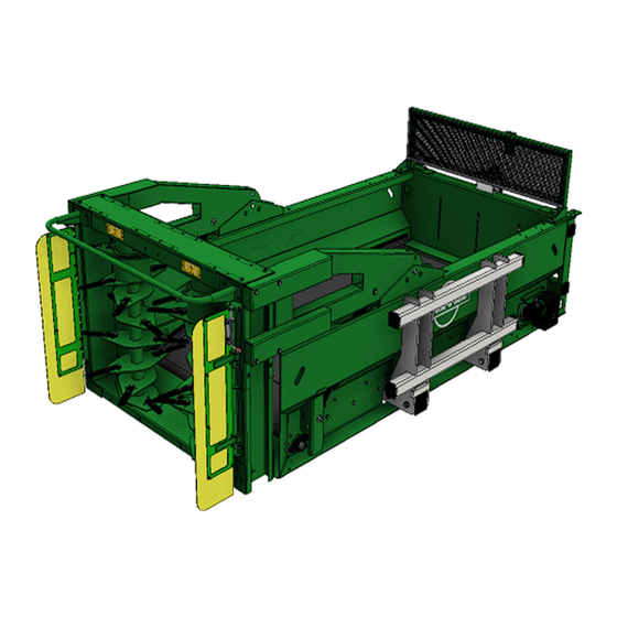
________4. Adjustment and Operation 4.0 Adjustment/Operation Fig. 4.01: Spread-A-Bale 4.1 Description Spread-A-Bale is designed specifically for use with a Loader, for both rectangular and round bales and spread them evenly in a welfare friendly manner. It is truly self- loading and is capable from the bale stack. -
Page 17: Control
See control adjustments @ 4.11 With the Loader auxiliary hydraulic control The unit is designed for a in neutral the Spread-A-Bale unit is maximum hydraulic flow rate inactive. of 50 litres per minute to the rotors and 5 litres per minute 4.3 First Operation... -
Page 18: Removing The Bale Twine Or String
4.8 Spreading Position the Spread-A-Bale in front of the When the bale reaches the rear face of area to be covered, elevating, and/or the unit reduce engine revs and cut the extending the Loader Boom as required. -
Page 19: Detachment
Before any adjustments are made the unit It is important that the Spread-A-Bale is should be placed on the ground in a stable moved about the farm best positioned for position and the power unit switched off the maximum all round vision and stability with the key removed. -
Page 20: Checks
________4. Adjustment and Operation Factory setting for the above is midway. table at the back for the correct bolt A good speed for the belt to travel is torques. approx. 45 seconds for the joiner to travel the length of the floor. Valve 2 - Belt Flow Diverter Valve The speed of the rotors must not be increased above the... -
Page 21: Servicing And Maintenance
_______5. Servicing and Maintenance This section describes the operations to 5. Servicing and correctly service the Spread-A-Bale unit. Maintenance These instructions are of an informative nature since they can vary due to climatic conditions and the type of work and Follow the safety instructions for frequency of operation of the unit. -
Page 22: Preparing For Storage
_______5. Servicing and Maintenance The mounting is to be on the rails after changing a hose check for leaks. identified above either side of the unit Dispose of any oil, old hydraulic pipes and vertical centre line using bolts capable of cleaning equipment in a safe manner. -
Page 23: Changing A Belt Bearing
_______5. Servicing and Maintenance of stiff fencing style wire make the necessary to adjust the belt once the temporary joint. machine has been run. Using a flame, melt the end of the Tips: plastic-coated joining cable to form a Melt the end of the joining cable cone/ point. -
Page 24: Changing A Rotor Motor
_______5. Servicing and Maintenance 5.12 Changing a Rotor 5.14 Operator Support Motor If you have a problem, please contact your dealer. They will endeavour to solve any This is one of the more complex tasks that problems which may occur and provide can be undertaken. -
Page 25: Overview Of Lubricating Points
_______5. Servicing and Maintenance 5.16 Overview of 5.17 Lubricating the Lubricating Points Machine Please read the section entitled "Using Lubrication Points Interval Lubricants" carefully before lubricating the Belt Bearings 50 Hours machine. Rotor Bearings 50 Hours The machine must be lubricated regularly in order for it to remain serviceable. - Page 26 _______5. Servicing and Maintenance Always exercise extreme care and Measures in case of injury through observe the recommended hygiene rules when handling mineral oil products. Details of these handling regulations can Eyes: be found in information provided by the Should any oil be splashed into your eyes, health authorities.
-
Page 27: Hydraulic Oil Specification
_______5. Servicing and Maintenance 5.19 Hydraulic Oil Specifications Please refer to your telescopic handler specifications; on supply the Spread-A- Bale unit will be filled with oil to the following specification: Viscosity @ 40°C....... 59 cSt Viscosity @ 100°C....9.4 cSt Viscosity index....…………..140 Density......…. -
Page 28: Faults And Remedies
5 seconds before using any throttle. DO NOT rev the machine. This usually results in the pressure relief valve blowing and poorer performance. WARM OIL – make sure that the handler is warm before using the Spread-a-Bale. The hydraulic oil needs to be at working temperature before the Spread-a-Bale will function correctly. - Page 29 7. Hydraulic Circuit Schematic 7. Hydraulic Circuit Schematic Drawing Flows shown when spreading Rotor Rotor Motor Motor Head Hydraulic Manifold Main Hydraulic Manifold Motor...
Need help?
Do you have a question about the Maxi and is the answer not in the manual?
Questions and answers