
Related Manuals for Solo UNO


Summary of Contents for Solo UNO
- Page 1 UART and USB User Manual SOLO UNO SOLO MINI SOLO BETA SOLO Motor Controllers Firmware versions supported: 0x0000B009 or later...
- Page 2 SOLO Communication Manual - UART and USB Revision History: Revision Date Changes V1.0.0 06/09/2021 First Release V1.0.1 30/09/2021 SOLO MINI added www.solomotorcontrollers.com September 2021 - Revision V_1.0.1 Copyright © 2021, All right Reversed. SOLO motor controllers.
-
Page 3: Table Of Contents
SOLO Communication Manual - UART and USB Contents: Purpose of this user manual UART and USB Access points on SOLO UNO: UART and USB Access points on SOLO MINI: UART or USB Hardware Settings: UART/USB Packets formation _ Commanding and Feedbacks: Memory Assignment for Write Commands:... - Page 4 0x84 : Phase-A Current 0x85 : Phase-B Current 0x86 : BUS Voltage (Input Supply / Battery) 0x87 : DC Motor Current (IM) 0x88 : DC Motor Voltage (VM) www.solomotorcontrollers.com September 2021 - Revision V_1.0.1 Copyright © 2021, All right Reversed. SOLO motor controllers.
- Page 5 0xAD : Sensorless Observer Filter Gain for Normal BLDC-PMSM Motors 0xAE : Sensorless Observer Filter Gain for Ultra Fast BLDC-PMSM Motors 0xB0 : Motor’s Angle www.solomotorcontrollers.com September 2021 - Revision V_1.0.1 Copyright © 2021, All right Reversed. SOLO motor controllers.
- Page 6 Digital Position Control using Quadrature Encoders Examples: Digital Position Control of a Brushless Motor using Encoders: Digital Position Control of a DC Brushed Motor using Encoders: www.solomotorcontrollers.com September 2021 - Revision V_1.0.1 Copyright © 2021, All right Reversed. SOLO motor controllers.
-
Page 7: Purpose Of This User Manual
Manual is to give a clear idea about how to setup and utilize SOLO communication networks powered by UART or USB and what is the purpose of each command existing in our command lists. -
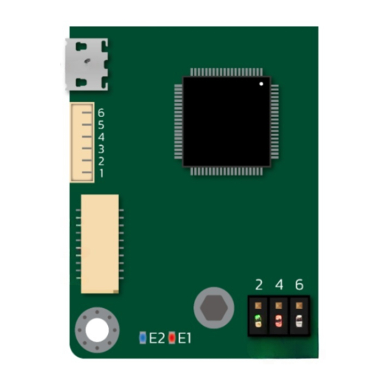
Page 8: Uart And Usb Access Points On Solo Uno
Figure 1- UART and USB access points on SOLO UNO UART TX is not +5V tolerant on SOLO UNO, as it’s an output pin with signal leveled at 3.3V which is compatible with all Arduino and Raspberry Pi modules, connection of this pin to +5V rated signals will damage the device. -
Page 9: Uart And Usb Access Points On Solo Mini
Figure 2- UART and USB access points on SOLO MINI UART TX is not +5V tolerant on SOLO MINI, as it’s an output pin with signal leveled at 3.3V which is compatible with all Arduino and Raspberry Pi modules, connection of this pin to +5V rated signals will damage the device. -
Page 10: Uart Or Usb Hardware Settings
In case of using USB connection, it will be recognized as a “Virtual COM Port (VCP)”, and the notion of “Baud-rate” will not be relevant as SOLO has a native USB-2 communication and the data-rate is defined by USB-2 ratings, however you can select any desired baud-rate for this port in VCP mode. -
Page 11: Uart/Usb Packets Formation _ Commanding And Feedbacks
SOLO’s in a network, so each of them can be assigned to a unique address. The default value of the address is set at zero. - Page 12 1. Commands to Write or Set something, these commands as their name suggests, will allow the user to tune a parameter inside of SOLO or set a value for the controllers like the desired speed or torque and so on, beside putting the right COMMAND code, the DATA section is used to write the desired value in desired register in SOLO.
-
Page 13: Memory Assignment For Write Commands
Once a parameter is written into SOLO, depending on the nature of the command two scenarios for storing the value will occur, either it will be stored on volatile memory of SOLO and resets to default after power recycling or it will be saved on non-volatile memory of SOLO and remembered after even power recycling and forever until it’s being overwritten or changed. -
Page 14: Data Types
SOLO Communication Manual - UART and USB DATA Types: The data types in SOLO are categorized into three main types as shown in table below: Name Value Size[bits] Range Resolution UINT32 Unsigned [0 to 4,294,967,295] +/- 1 Integer [-2,147,483,647 to... -
Page 15: Data Types Conversions
3) The float number = (data in Decimal format taken from step “2” /131072 ) * -1 Example1 _ positive Numbers: Data read from SOLO is “0x00030000” So it’s a Positive Numbers Conversion since the data read from SOLO is less than or equal to 0x7FFE0000 so the conversion will be: 1) Decimal (0x00030000) = 196608 2) 196608 / (131072) = 1.5... -
Page 16: Converting Float Data Type To Sfxt(32-17) Data Type
Converting float data type to Sfxt(32-17) data type : If the DATA section of a packet to be sent to SOLO, contains a number in Fixed-Point format, you can use the following two methods to convert your real world float number into a Sfxt(32- 17) data type depending on the sign of the float data and whether if it’s a positive value or a... -
Page 17: Converting 32 Bits Hex Data To Signed Int32 Format
Converting 32 bits Hex data to signed INT32 format: If you want to convert a DATA part of a packet read from SOLO into the real world Int32 format, based on the sign of the DATA you will fact the following two conditions for the conversion:... -
Page 18: Converting Signed Int32 To 32Bits Hex Format
If you want to convert an INT32 value to a Hex formatted number to place in the DATA part of a packet to send to SOLO, based on the sign of the data you want to send, you will face the... -
Page 19: Write Commands
SOLO Communication Manual - UART and USB WRITE Commands: Below all the existing Write commands to set a value in SOLO with their description for UART or USB communication for are listed. 0x01 : Set Device Address Code: 0x01 Set Device Address... -
Page 20: 0X02 : Commanding Mode
Once in Analogue Mode some configuration can be done only at hardware level, as the table below suggests, everything else outside of the below table can be set only through sending data packets to SOLO through UART, USB or CAN bus. -
Page 21: 0X03 : Current Limit
This command sets the amount of desired current that acts in torque generation. In 3-phase motors this is called Iq or quadrature current as SOLO operates in FOC mode, however for DC brushed motors this value sets the reference for IM in DC brushed motors. -
Page 22: 0X05 : Speed Reference
RPM* Description: This command defines the speed reference for SOLO once it’s in Digital Speed Mode, as in analogue mode the reference is set through the “S/T” input pin with analogue voltages or PWM pulses once SOLO is in Speed Mode. -
Page 23: 0X06 : Power Reference
0 or 1 Description: By putting 1 in the DATA section of a packet sent with this command, SOLO will start identifying the electrical parameters of the Motor connected, The identification will take 1 second to be done and after that the Motor Inductance, Resistance and some internal parameters are Identified ( or re-identified). -
Page 24: 0X09 : Output Pwm Frequency (Switching Frequency)
Motor and the SOLO unit itself if the Motor under control can not support such high frequencies. -
Page 25: 0X0B : Speed Controller Ki Gain
This is the integral gain of the PI controller that SOLO uses to control to stabilize the speed of a motor on a given reference point, This gain is normally for most motors takes a value in between 0.0001 to 0.01 but there might be some cases that you need to go even higher, the... -
Page 26: 0X0D : Motor's Phase Or Armature Resistance
[1-254] Description: This command sets the number of the Poles of a 3-phase motor commissioned with SOLO, in case of BLDC or PMSM motors, the Number of poles is equal to the number of magnets on the rotor of the Motor, for ACIM motors, the user has to refer to the technical datasheet of their motor to find this parameter. -
Page 27: 0X10 : Incremental Encoder's Lines
Uint32 Description: This command resets the device address of any connected SOLO to zero, to properly form this command the user has to put “0xFF” as the Device Address inside the packet being sent to SOLO with DATA filled with zeros as below:... -
Page 28: 0X13 : Feedback Control Mode
Memory Storage Default Value Uint32 [0-2] Description: This command sets the type of the feedback control SOLO has to operate with based on table below both in Analogue or Digital Mode: DATA Operation 0 (0x00000000) Operates in Sensor-less feedback Mode... -
Page 29: 0X15 : Motor Type
0x15, the user has to note that in Analogue Mode the Motor Type is only selected by Piano Switch in SOLO UNO using PIN 1 and 2 and on SOLO MINI it’s selected by M1 and M2 pins on the “I/O Port” (refer to respective SOLO user manual to know more) -
Page 30: 0X16 : Control Mode Type
Mode based on the following table, in Analogue Mode this functionality is selected by using Piano switch PIN 4 in SOLO UNO and using FN pin on SOLO MINI for only Torque and Speed controlling functionalities. (refer to respective SOLO user manual to know more) -
Page 31: 0X18 : Current Controller Ki Gain (Torque Controller)
PI controller that controls the current (torque) inside of the motor both in Analogue or Digital Mode, this value is automatically identified by SOLO after Motor Identification but in any case it’s possible for the user to alter this value as they like. After changing this value manually, for them to take effect a power recycle is required. -
Page 32: 0X19 : Monitoring Modes Enable/Disable
DATA is sent using the command code of 0x19 in a data packet to SOLO, this functionality works both in Digital and Analogue Control Modes. This Mode is recommended to be used only for inspections and during system evaluations, as its activation puts a heavy processing burden on the main DSP on SOLO. -
Page 33: 0X1A : Magnetizing Current Reference (Id)
This command sets the desired magnetizing current (Id) required for controlling ACIM motors in FOC in Amps, it can be used only in Closed-loop digital mode, since in Analogue mode the Magnetizing current reference is set throug Pin “P/F” (refer to SOLO user manual to know more) -
Page 34: 0X1C : Position Controller Kp Gain
Uint32 Description: This command resets the position counter back to zero if in the DATA part of the packet the value of “0x00000001” is placed. www.solomotorcontrollers.com September 2021 - Revision V_1.0.1 Copyright © 2021, All right Reversed. SOLO motor controllers. -
Page 35: 0X20 : Overwrite The Errors
DATA part with only zeros inside, the whole error register will be overwritten. Once the error is over-written if it’s cause of existence is removed, SOLO will return back to normal operation, otherwise it will stay in fault mode without any switching at the output. -
Page 36: 0X21 : Sensorless Observer Gain For Normal Bldc-Pmsm Motors
Inductance over Resistance of the Motor’s phases. This observer gain will be used both in Analogue and Digital Mode for Sensor-less operations and the gain can be modified dynamically in run-time. www.solomotorcontrollers.com September 2021 - Revision V_1.0.1 Copyright © 2021, All right Reversed. SOLO motor controllers. -
Page 37: 0X23 : Sensorless Observer Gain For Dc Brushed Motors
[0.01 - 16000 ] Description: This command sets how fast the observer should operate once SOLO is in sensorless mode with normal BLDC-PMSM selected as the Motor type. Generally this gain can have values from 1 to 1000 and the lower the gain, the better will be the performance in Higher speeds. -
Page 38: 0X25 : Sensorless Observer Filter Gain For Ultra Fast Bldc-Pmsm Motors
This command sets the baud-rate of the UART line, currently there are two baudrates supported by SOLO, and they can be selected by sending either 0 or 1 in DATA section of the packet with command code of “0x26”, if the value of the baud rate is changed, to make it effective a power recycle is necessary. -
Page 39: 0X27 : Encoder Or Hall Sensors Calibration Start/Stop
C.C.W direction, the value must be between 0 to 1 and it gets automatically updated each time after sensor calibration, however the users can insert their desired value dynamically. www.solomotorcontrollers.com September 2021 - Revision V_1.0.1 Copyright © 2021, All right Reversed. SOLO motor controllers. -
Page 40: 0X29 : Per-Unit Encoder Or Hall Sensor Clockwise Offset
This command defines the acceleration value of the Speed for speed controller both in Analogue and Digital modes in Revolution per square seconds, this value only has effect once SOLO is in Speed control mode and it will be ignored once in Torque or Position Mode. www.solomotorcontrollers.com September 2021 - Revision V_1.0.1... -
Page 41: 0X2B : Speed Deceleration Value
Analogue and Digital modes in Revolution per square seconds, this value only has effect once SOLO is in Speed control mode and it will be ignored once in Torque or Position Mode. Defining deceleration can reduce the regenerative power going back to supply as the speed reduces slowly. -
Page 42: 0X2C : Can Bus Baud Rate
This command sets the baud rate of CAN bus in CANOpen network based on the following table if the DATA in the packet with command code of 0x2C is used, after changing the baud rate a power cycle is required for SOLO so the new baud rate can take effect. DATA... -
Page 43: Read Commands
SOLO Communication Manual - UART and USB Read Commands: Below all the existing command codes to read a value from SOLO with their description for UART or USB communication for SOLO are listed, to read a value from SOLO, the proper command code should be used with DATA section filled with Zeros (unless specified) for the request of the feedback. -
Page 44: 0X84 : Phase-A Current
BUS Voltage (Input Supply / Battery) Data Type Data Range Units Memory Storage Default Value Sfxt(32-17) [0 - 60] Volts Description: This command reads the input BUS voltage. www.solomotorcontrollers.com September 2021 - Revision V_1.0.1 Copyright © 2021, All right Reversed. SOLO motor controllers. -
Page 45: 0X87 : Dc Motor Current (Im)
Memory Storage Default Value Sfxt(32-17) [0.0 - 16000.0] Description: This command reads the value of the Speed controller Kp gain, set for Digital mode operations. www.solomotorcontrollers.com September 2021 - Revision V_1.0.1 Copyright © 2021, All right Reversed. SOLO motor controllers. -
Page 46: 0X8A : Speed Controller Ki Gain
Default Value Sfxt(32-17) [0.2 - 32.0] Amps Description: This command reads the value of the current limit set for SOLO in closed-loop digital operation mode. www.solomotorcontrollers.com September 2021 - Revision V_1.0.1 Copyright © 2021, All right Reversed. SOLO motor controllers. -
Page 47: 0X8D : Quadrature Current (Iq)
Data Type Data Range Units Memory Storage Default Value Uint32 [1 - 254] Description: This command reads the number of Poles set for 3-phase motors. www.solomotorcontrollers.com September 2021 - Revision V_1.0.1 Copyright © 2021, All right Reversed. SOLO motor controllers. -
Page 48: 0X90 : Incremental Encoder's Lines
Memory Storage Default Value Uint32 [1 - 200,000] 1000 Description: This command reads the number of physical Incremental encoder lines set on SOLO. 0x91 : Current Controller Kp Gain Code: 0x91 Current Controller Kp Gain Data Type Data Range Units... -
Page 49: 0X93 : Board Temperature
Sfxt(32-17) [0.0 - 0.2] Henry Description: This command reads the Phase or Armature Inductance of the 3-phase or DC brushed motor connected to SOLO respectively. www.solomotorcontrollers.com September 2021 - Revision V_1.0.1 Copyright © 2021, All right Reversed. SOLO motor controllers. -
Page 50: 0X96 : Speed Feedback
Analogue mode the motor type shown is the Motor type selected by Piano switch in SOLO UNO ro by the M1 and M2 pins in SOLO MINI in Analogue mode (refer to respective SOLO user manual to know more), to see the Motor type selected in Digital Mode, first the user has to put the system in Digital Mode using command code of “0x02”. -
Page 51: 0X99: Feedback Control Mode
Data Range Units Memory Storage Default Value Uint32 0 or 1 Description: This command reads the actual commanding mode that SOLO is operating , based on table below : DATA Operating Mode 0 (0x00000000) SOLO is in Analogue Mode 1 (0x00000001) SOLO is in Digital Mode www.solomotorcontrollers.com... -
Page 52: 0X9B : Control Mode Type
Data Range Units Memory Storage Default Value Uint32 [0-30,000] 30,000 Description: This command reads the value of the speed limit set on SOLO. 0x9D : PositionController Kp Gain Code: 0x9D PositionController Kp Gain Data Type Data Range Units Memory Storage... -
Page 53: 0X9E: Position Controller Ki Gain
Memory Storage Default Value Int32 [-2,147,483,647 to Quad-Pulses 2,147,483,647] Description: This command reads the number of counted pulses from the Incremental Encoder in Quadrature manner. www.solomotorcontrollers.com September 2021 - Revision V_1.0.1 Copyright © 2021, All right Reversed. SOLO motor controllers. -
Page 54: 0Xa1 : Error Register
, the error has occurred if the respective bit is set to 1, The errors can be over-written using command code 0x20 , if an error occurs, until it’s not over- written, SOLO will send out the Error register packet every 300 Milliseconds. Bit Number... -
Page 55: 0Xa2 : Firmware Version
Memory Storage Default Value Uint32 Description: This command reads the Firmware version existing currently on the SOLO unit, the DATA section of the received command will contain a Number like “0x0000B009” which will indicate the firmware version. 0xA3 : Hardware Version... -
Page 56: 0Xa5 : Speed Reference
2,147,483,647] Description: This command reads the desired position reference set for the Motor to follow in Digital Closed-loop Position mode in terms of quadrature pulses. www.solomotorcontrollers.com September 2021 - Revision V_1.0.1 Copyright © 2021, All right Reversed. SOLO motor controllers. -
Page 57: 0Xa8 : Power Reference
Default Value Sfxt(32-17) [0 - 100] Description: This command reads the desired Power reference for SOLO to apply in Digital Open-loop speed control mode for 3-phase motors in terms of percentage. 0xA9 : Desired Direction of Rotation Code: 0xA9 Desired Direction of Rotation... -
Page 58: 0Xab : Sensorless Observer Gain For Ultra-Fast Bldc-Pmsm Motors
Units Memory Storage Default Value Sfxt(32-17) [0.01 - 16000 ] Description: This command reads the value of Sensorless Observer Filter Gain for Normal BLDC-PMSM Motors. www.solomotorcontrollers.com September 2021 - Revision V_1.0.1 Copyright © 2021, All right Reversed. SOLO motor controllers. -
Page 59: 0Xae : Sensorless Observer Filter Gain For Ultra Fast Bldc-Pmsm Motors
Units Memory Storage Default Value Sfxt(32-17) [0.0 - 1.0] Per Unit Description: This command reads the per-unit Encoder or Hall sensor offset in C.C.W direction. www.solomotorcontrollers.com September 2021 - Revision V_1.0.1 Copyright © 2021, All right Reversed. SOLO motor controllers. -
Page 60: 0Xb2 : Per-Unit Encoder Or Hall Sensor Clockwise Offset
Units Memory Storage Default Value Uint32 Bits/s 937500 Description: This command reads Baud Rate selected on SOLO unit to communicate through UART line as shown in table below: DATA Baud-Rate [bits/s] 0 (0x00000000) 937500 (compatible with 921600) 1 (0x00000001) 115200... -
Page 61: 0Xb5 : Speed Deceleration Value
This command Reads the baud rate of CAN bus in CANOpen network based on the following table. DATA CAN bus Baud Rate [ kbits/s ] 0 (0x00000000) 1000 1 (0x00000001) 2 (0x00000002) 3 (0x00000003) 4 (0x00000004) www.solomotorcontrollers.com September 2021 - Revision V_1.0.1 Copyright © 2021, All right Reversed. SOLO motor controllers. -
Page 62: Uart/Usb Packet Formation Examples
_ NOTE : The SPACE character in between the bytes below, is just for readability purposes and ASCII code of SPACE shouldn’t be sent to SOLO, all the bytes should be sent to SOLO one after another with nothing in between. -
Page 63: Change The Direction Of Rotation
FF FF 00 0F 00 00 00 08 00 FE To check the written value: Read the number of Poles: FF FF 00 8F 00 00 00 00 00 FE www.solomotorcontrollers.com September 2021 - Revision V_1.0.1 Copyright © 2021, All right Reversed. SOLO motor controllers. -
Page 64: Change Or Set/Reset The Device Address
Change or Set/Reset the Device address: The default device address on each SOLO upon delivery is 0x00, but you can change this value to anything in between 0x00 to 0xFE (254). For example, below you can see an example of how to change the device address from 0 to 1, and then check the changes. -
Page 65: Set The Output Switching Frequency (Pwm Frequency)
Set the output switching Frequency (PWM frequency): On SOLO you can have any switching frequency from 8kHz to 80kHz at the output depending on your need and the inductance of your motor, in general the Motors with low inductance need higher switching frequencies to be able to keep their current stabilized and controlled. -
Page 66: Digital Sensorless Torque Control Of A Bldc Motor
3. Make sure the motor Identification is done. As long as the piano switch number 5 is DOWN in SOLO UNO or the Control Mode Switch on SOLO MINI is on C.L, you can send the following commands in order to control the torque of your brushless Motor. -
Page 67: Digital Sensorless Speed Control Of A Brushless Motor
3. Make sure the motor Identification is done. As long as the piano switch number 5 is DOWN in SOLO UNO or the Control Mode Switch on SOLO MINI is on C.L, you can send the following commands in order to control the torque of your brushless Motor. -
Page 68: Digital Speed Control Of A Brushless Motor Using Encoders
3. Make sure the motor Identification is done. As long as the piano switch number 5 is DOWN in SOLO UNO or the Control Mode Switch on SOLO MINI is on C.L, you can send the following commands in order to control the torque of your brushless Motor. -
Page 69: Digital Sensorless Speed Control Of A Dc Brushed Motor
3. Make sure the motor Identification is done. As long as the piano switch number 5 is DOWN in SOLO UNO or the Control Mode Switch on SOLO MINI is on C.L, you can send the following commands in order to control the torque of your brushless Motor. -
Page 70: Digital Speed Control Of A Dc Brushed Motor Using Encoder
3. Make sure the motor Identification is done. As long as the piano switch number 5 is DOWN in SOLO UNO or the Control Mode Switch on SOLO MINI is on C.L, you can send the following commands in order to control the torque of your brushless Motor. -
Page 71: Digital Open-Loop Control Of A Brushless Motor
SOLO UNO or by putting the Control Mode Switch on O.L on SOLO MINI As long as the piano switch number 5 is UP in SOLO UNO or the Control Switch Mode is on O.L in SOLO MINI, you can send the following commands in order to control the speed of your brushless motor in open-loop mode. -
Page 72: Digital Sensorless Closed-Loop Speed Control Of An Ac Induction Motor
3. Make sure the motor Identification is done. As long as the piano switch number 5 is DOWN in SOLO UNO or the Control Mode Switch on SOLO MINI is on C.L, you can send the following commands in order to control the torque of your brushless Motor. -
Page 73: Digital Position Control Using Quadrature Encoders Examples
Position Control Resolution [deg] = �������������� ������������ ���� ��ℎ������������ ���������� ∗ 4 The position references sent to SOLO are from the signed Int32 data type and they can be anything from -2,147,483,647 to +2,147,483,647 in decimal form which are indicating the desired position to be reached in terms of quadrature pulses. -
Page 74: Digital Position Control Of A Brushless Motor Using Encoders
Before sending the following commands you must do the following steps at least once: 1. Turn ON SOLO 2. Put SOLO in closed-loop (using Piano switch on SOLO UNO or Control Mode Switch on SOLO MINI) 3. Make sure the motor Identification is done. -
Page 75: Digital Position Control Of A Dc Brushed Motor Using Encoders
Before sending the following commands you must do the following steps at least once: 1. Turn ON SOLO 2. Put SOLO in closed-loop (using Piano switch on SOLO UNO or Control Mode Switch on SOLO MINI) 3. Make sure the motor Identification is done.
Need help?
Do you have a question about the UNO and is the answer not in the manual?
Questions and answers