Table of Contents
Advertisement
Quick Links
SOLO PICO User Manual
Part Number: SLP0123_5816
Product Description
SOLO PICO with part number of
is a member of the SOLO motor
SLP0123_5816
controllers family of devices capable of driving
and controlling various types of electrical
motors like DC brushed, BLDC, PMSM and EC
coreless motors in a single platform. They are
made to be easy to use with state of art
technologies and Dual Core parallel processing
architecture on top of FOC control methods.
SOLO PICO supports sensor-based Torque,
Speed and Position controlling plus other
options like full digital and analog controls and
active safety measures to keep the
applications safe from unforeseen behaviors.
Features
● Easy to use
● Drives and Controls DC brushed,
BLDC, PMSM and EC coreless motors
● Torque, Speed and Position controlling
● Four Quadrant Regenerative operation
● Automatic parameter Identification
and self-tuning
● Safe Torque off (STO) input
● USB, UART and CANopen
● Supports PT1000 temperature sensors
● Sleep mode with current consumption
of 200µA
Modes of Operation
● Analogue or Digital commanding
● Torque Control
● Speed Control
● Position Control
www.solomotorcontrollers.com
July 2023 - Revision V_1.0.1
Power Range
Supply Voltage Range : 8- 58 VDC
Peak Current: 32A peak to peak
Continuous Current: 16A
Commands and feedbacks Source
Copyright © 2023, All right Reversed. SOLO motor controllers.
● Field Oriented Control with Nested
Position-Speed-Torque loops
● Dual Core with Parallel Processing
Architecture
● Bus over-voltage, Bus under-voltage ,
over-current and over temperature
protections
● Full Digital and Analogue Control
● Space Vector Modulation (SVPWM)
● Embedded Motion Profile (St-Curve)
for Position and Speed
● 0-5V Analogue/ PWM inputs for Speed
or Torque control
● Analogue torque and speed feedbacks
● Quadrature Encoder and Hall sensor
inputs
● Isolated UART, USB and CAN bus
1
Advertisement
Table of Contents

Related Manuals for Solo PICO


Summary of Contents for Solo PICO
- Page 1 ● Speed Control ● Analogue torque and speed feedbacks ● Position Control ● Quadrature Encoder and Hall sensor inputs ● Isolated UART, USB and CAN bus www.solomotorcontrollers.com July 2023 - Revision V_1.0.1 Copyright © 2023, All right Reversed. SOLO motor controllers.
- Page 2 ● Automotive Industries ● Household Appliances ● Medical Devices ● Aerospace ● Textile Industry ● Automated Guided Vehicles (AGVs) ● Heating, Ventilation and Air-Conditioning (HVAC) www.solomotorcontrollers.com July 2023 - Revision V_1.0.1 Copyright © 2023, All right Reversed. SOLO motor controllers.
- Page 3 Hazards that can cause serious damages or injuries. Caution Hazards that can cause minor injuries or material damage. Recommendations, tips, references to other documentation. Essential or useful accessories. www.solomotorcontrollers.com July 2023 - Revision V_1.0.1 Copyright © 2023, All right Reversed. SOLO motor controllers.
- Page 4 SOLO PICO User Manual Part Number: SLP0123_5816 Revision History: Revision Date Changes Firmware version V1.0.0 11/06/2023 First Release 0x0000B00F www.solomotorcontrollers.com July 2023 - Revision V_1.0.1 Copyright © 2023, All right Reversed. SOLO motor controllers.
-
Page 5: Table Of Contents
Absolute Maximum Voltage Ratings: Overview of the product Functional Block Diagram: Theory of Operation: FOC control Architecture in SOLO PICO for 3-phase Motors: Cascade control Architecture in SOLO PICO for DC Motors: SOLO PICO’s Interactional Sections: Connectors and Sections: Sections [4, 5, 6] - Motor Outputs... - Page 6 Embedded MCU Boards Using CANopen: General Wiring Considerations in SOLO PICO: 1- Avoid running feedbacks and power wires together 2- Avoid making ground loops Temperature and Max Current Behaviour: www.solomotorcontrollers.com July 2023 - Revision V_1.0.1 Copyright © 2023, All right Reversed. SOLO motor controllers.
-
Page 7: Power Specifications
Maximum Peak Output Current 32 peak to peak Maximum Continuous Output Current Maximum Continuous Output Power Internal Bus Capacitance µF Switching Frequency 8 to 80 (Output PWM Frequency) www.solomotorcontrollers.com July 2023 - Revision V_1.0.1 Copyright © 2023, All right Reversed. SOLO motor controllers. -
Page 8: Control And Timings Specifications
Speed controller Loop execution time µs Position controller Loop sampling time µs Position controller Loop execution time µs Maximum Encoder Frequency (Pre-Quad) Current Measurement Resolution www.solomotorcontrollers.com July 2023 - Revision V_1.0.1 Copyright © 2023, All right Reversed. SOLO motor controllers. -
Page 9: Thermal Specifications
Natural Convection Mechanical Specifications: Description Units Values Size (H x W x D) 19.2 x 67.73 x 56.82 Weight (without heatsink) Form Factor Wall Mount www.solomotorcontrollers.com July 2023 - Revision V_1.0.1 Copyright © 2023, All right Reversed. SOLO motor controllers. -
Page 10: Mechanical Dimensions ( No Heatsink )
SOLO PICO User Manual Part Number: SLP0123_5816 Mechanical Dimensions ( No Heatsink ): All the measurements are in millimeters. www.solomotorcontrollers.com July 2023 - Revision V_1.0.1 Copyright © 2023, All right Reversed. SOLO motor controllers. -
Page 11: Mechanical Dimensions ( With Heatsink )
SOLO PICO User Manual Part Number: SLP0123_5816 Mechanical Dimensions ( With Heatsink ): Heatsinks can be provided upon costumer request. All the measurements are in millimeters. www.solomotorcontrollers.com July 2023 - Revision V_1.0.1 Copyright © 2023, All right Reversed. SOLO motor controllers. -
Page 12: Absolute Maximum Voltage Ratings
EB (Encoder channel B) Input +5.25 [10] EC (Encoder channel C) Input +5.25 [10] Input -0.5 +5.5 [10] Output -0.5 +5.5 [10] [10] [10] Output +5.5 www.solomotorcontrollers.com July 2023 - Revision V_1.0.1 Copyright © 2023, All right Reversed. SOLO motor controllers. -
Page 13: Overview Of The Product
Brushless DC and PMSM motors up to 58V DC with the supply voltage and the continuous current of up to 16 Amps, this will enable SOLO PICO to be utilized in wide range of products and projects and eventually speeding up the developments and time to market for its users. -
Page 14: Functional Block Diagram
SOLO PICO User Manual Part Number: SLP0123_5816 Functional Block Diagram: Figure 1 - Functional Block Diagram of SOLO PICO www.solomotorcontrollers.com July 2023 - Revision V_1.0.1 Copyright © 2023, All right Reversed. SOLO motor controllers. -
Page 15: Theory Of Operation
Brushless DC and PMSM this topology is known as Field Oriented Control or Vector Control. In general we can divide the whole control architecture of SOLO for two different types of Motors, the 3-phase motors that can be seen in Figure 3 and Brushed DC motors that can be seen in Figure 4 below. -
Page 16: Foc Control Architecture In Solo Pico For 3-Phase Motors
FOC control Architecture in SOLO PICO for 3-phase Motors: Figure 3 - FOC Control Architecture of SOLO PICO for 3-phase Motors As can be seen in Figure 3, to control any of the Torque, Speed and even position of a 3-phase motor in FOC fashion, there is a need to have at least 4 different feedbacks: www.solomotorcontrollers.com... -
Page 17: Cascade Control Architecture In Solo Pico For Dc Motors
3- Position Feedback: This feedback comes from external sensors like Encoders, and it enables the Servo-Driving Capabilities of SOLO 4- Motor Electrical Angle: This feedback is essential for any type of closed-loop control on SOLO, this feedback is Measured by SOLO internally. -
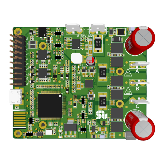
Page 18: Solo Pico's Interactional Sections
Part Number: SLP0123_5816 SOLO PICO’s Interactional Sections: SOLO PICO can be decomposed into 10 main interactional sections as shown in Figure 5, all the sections will be explained in detail and their electrical and maximum ratings will be mentioned later in this user manual, the user has to make sure they don’t exceed those maximum ratings to avoid damaging themselves or the SOLO PICO unit. -
Page 19: Connectors And Sections
Motor Output 2 Motor Output 3 Description This connector of SOLO should be connected to the Motors’ wires. You can find out more about how to connect them by looking at the “SOLO PICO Wirings” Section, but in general for 3 phase motors the A,B,C pins should get connected to the 3 phase wires of the motor and for DC brushed motors only B and C pins are required to be connected to the motor. -
Page 20: Sections [2, 3] - Supply Inputs
Negative Voltage Input ( Ground ) Description This is the Power Supply input of SOLO and it can be supplied with any DC input voltages from 8 to 58 volts in continuous mode, depending on the voltage rating of the Motor Connected at the output. -
Page 21: Section [10] - Control I/O Port
Input of channel C of the Encoder or Hall position sensors Firmware Upgrade Mode is selected by grounding this PIN Ground of SOLO PICO UART protocol transmitter output UART protocol transmitter input www.solomotorcontrollers.com July 2023 - Revision V_1.0.1 Copyright © 2023, All right Reversed. SOLO motor controllers. - Page 22 Part Number: SLP0123_5816 Description This is the Control I/O port of SOLO that can be used in both Analogue or Digital Modes, It provides the sensor inputs ( like the encoders, temperature sensors) as well as other functionalities like Safe Torque Off or Sleep mode.
- Page 23 Part Number: SLP0123_5816 “Dir” PIN: This Direction control pin in Analogue Mode, accepting voltage levels of 0V or 3.3V/ 5V, by giving each of these values, the connected Motor to SOLO, will rotate in C.W. direction or C.C.W. direction. “P/F” PIN:...
- Page 24 PWM inputs, a 0% duty cycle to this pin , it will keep your motor’s speed at 0 RPM, and at the same time by applying 100% duty cycle or 5V Analogue input, SOLO will force your motor to go to the maximum speed based on the Motor’s type divided by ASRDC coefficient ( Analogue Speed Resolution...
- Page 25 To learn about how to Setup and calibrate your Incremental Encoders for SOLO PICO please visit this page on our website. To learn about how to Setup and calibrate your HALL sensors for SOLO PICO please visit this page on our website. www.solomotorcontrollers.com July 2023 - Revision V_1.0.1...
- Page 26 “zZ” PIN: By connecting this pin to ground the SOLO PICO will go into the Sleep mode, consuming less than 200µA, in sleep mode none of the functional activities of SOLO is accessible.to learn about it’s functionality please refere to “Wiring of Sleep Mode...
-
Page 27: Section [9] - Usb Connection
1 USB cable and the Motor connected at the output. Powering up SOLO with any DC input voltages from 8 to 58 volts is necessary when SOLO PICO is connected to the external Host by using USB cable (USB cable doesn’t power up SOLO itself). -
Page 28: Sections [7,8] - Functionality Leds
Error Indicator LED Description There are three LEDs on SOLO PICO, two of them are named as “E1” and “E2” and have functionalities as below: E2 : This is the status or heart-beat indicator, after the device startup, in case of having a safe boot up , it will start blinking and remain in the blinking state. -
Page 29: Section [1] - Power Up Led
Descriptions / Notes Power Up LED Description This LED will start glowing once SOLO is correctly powered up with a voltage from 8 to 58V. www.solomotorcontrollers.com July 2023 - Revision V_1.0.1 Copyright © 2023, All right Reversed. SOLO motor controllers. -
Page 30: Connectors And Their Matings Part Number
SOLO PICO User Manual Part Number: SLP0123_5816 Connectors and their Matings Part Number: Section Manufacturer Mating Part Number [2,3,4,5,6] Molex 0190160085 [10] Amphenol ICC (FCI) 76342-310LF 89898-310LF 71609-310LF www.solomotorcontrollers.com July 2023 - Revision V_1.0.1 Copyright © 2023, All right Reversed. SOLO motor controllers. -
Page 31: Analogue Versus Digital Control In Solo Pico
Part Number: SLP0123_5816 Analogue versus Digital Control in SOLO PICO The “Analogue” control in SOLO puts the unit in a mode that can accept Torque or Speed references along with Current limit and the Direction of the rotation through an analogue mean... -
Page 32: Solo Pico Wirrings
SOLO PICO User Manual Part Number: SLP0123_5816 SOLO PICO Wirrings The wiring legends in SOLO PICO are as below: Wiring Legend: Shape Description SOLO PICO ground External ground(peripheral ground, PLC ground, Embedded MCU boards ground, External supply ground) Fuse, the value must be selected based on the system... -
Page 33: Safe Torque Off (Sto) Wiring
The “Safe Torque off” is a hardware level protection that reliably disconnects the energy supply to the motor in your particular application. For proper working of SOLO PICO providing STO wiring is mandatory. The STO has a negative logic, meaning that once the STO line is powered up to a high state ( e.g. -
Page 34: 2- Wire Sto To A Safety Relay Using Internal +5V Supply Voltage
2- Wire STO to a safety relay using internal +5V supply voltage: As shown in Figure 8 the +5V voltage of SOLO PICO is used to wiring up STO inputs. The safety relay can be commanded from external commanding devices. -
Page 35: 3- By Passing Sto Without External Commanding Devices
3- By Passing STO without external commanding devices: As shown in Figure 8, the +5V voltage of SOLO PICO is used for wiring up STO input. This STO wiring is a very simple way to run SOLO as quickly as possible since it essentially bypasses the STO functionality . -
Page 36: Analogue Wiring In Solo Pico
As can be seen in Figure 10 the Dir pin is connected to controller NPN output and also is pulled up to +5V of SOLO PICO through a 2.2KΩ resistor. Also 0-5V analogue outputs are connected to S/T and P/F inputs. -
Page 37: 2- Analogue Wiring In Case Of Controller With Pnp Outputs
In order to effectively reduce picking up noises from other EMI sources, It’s recommended to connect cable shields to SOLO PICO ground or to controller ground only at one side. The SOLO PICO ground must be connected to controller ground www.solomotorcontrollers.com... -
Page 38: 3- Analogue Wiring In Case Of Embedded Mcu Boards
3- Analogue wiring in case of Embedded MCU Boards: SOLO PICO can be controlled by any Embedded MCU boards with 3.3V or 5V logic like Arduino, Raspberry Pi and so on. As can be see in Figure 12 the Dir is connected to any digital outputs of Embedded MCU Board, also S/T and P/F pins are connected to analogue or PWM outputs of Embedded MCU Board. -
Page 39: Wiring With Hall Sensors
In order to effectively reduce picking up noises from other EMI sources, It’s recommended to connect cable shields to SOLO PICO ground or to controller ground only at one side. The SOLO PICO ground must be connected to the Hall Sensor ground. -
Page 40: Wiring With Incremental Encoders
In SOLO PICO the Incremental Encoder can be wired in two different ways according to the type of encoder both in Differential or Single Ended fashion. 1- Wiring in case of Single Ended Incremental Encoders: As can be seen in Figure 14, channels A, B and C of Single Ended Encoder are connected to EA, EB and EC inputs of SOLO PICO respectively, EC is known as Index pulse or Z pulse. -
Page 41: 2- Wiring In Case Of Differential Incremental Encoders
In order to effectively reduce picking up noises from other EMI sources, It’s recommended to connect cable shields to SOLO PICO ground or to controller ground only at one side. The Incremental Encoder is powered using +5V output of SOLO PICO. -
Page 42: Wiring Of Sleep Mode Input
Wiring of DFU Mode input: As can be seen in Figure 17 and Figure 18 in order to put SOLO in DFU Mode, the DFU input (pin 17 of control connector) must be connected to ground (pin 18 of control connector). - Page 43 3. Turn ON SOLO ( both E2 and E1 LEDs will remain ON ) 4. Updated the firmware using our updater tool. 5. Turn OFF SOLO 6. Disconnect the DF pin from the Ground, and Turn SOLO ON ( E2 will start blinking and the unit will be operational ) www.solomotorcontrollers.com July 2023 - Revision V_1.0.1...
-
Page 44: Pt1000 Temperature Sensor Wiring
PT1000 temperature sensor wiring: PT1000 temperature sensor is a positive-temperature-coefficient resistor. As shown in Figure 19 in SOLO PICO by connecting a PT1000 temperature sensor to the TS pin, the temperature can be measured. Figure 19 - PT1000 temperature sensor wiring In order to measure the temperature do the following steps: 1. - Page 45 SOLO PICO User Manual Part Number: SLP0123_5816 Figure 20 - A sample PT1000 temperature sensor characteristic curve www.solomotorcontrollers.com July 2023 - Revision V_1.0.1 Copyright © 2023, All right Reversed. SOLO motor controllers.
-
Page 46: Analogue Torque And Speed Feedbacks And Wiring
Part Number: SLP0123_5816 Analogue Torque and Speed Feedbacks and Wiring: There are two analogue feedbacks in SOLO PICO. These analogue feedbacks generate an analogue voltage between 0-5V according to measured motor Speed and Torque in both directions. This feedback once the measure Speed or Torque is at 0 will stay at 2.5V ( mid-point), thus depending on the direction of the rotation, this feedback will either be greater than mid-point or smaller than that. - Page 47 Figure 23- Analogue Torque and Speed feedbacks wiring In order to effectively reduce picking up noises from other EMI sources, It’s recommended to connect cable shields to the SOLO PICO ground or to the Embedded MCU Board ground only at one side.
-
Page 48: Digital Mode Wirings
USB Interface Wiring By using USB connection, you have the access to the simplest form of wiring of SOLO PICO to be commanded using only a USB cable thanks to the digital control that it offers, in this mode the only thing you will need is a micro USB 2.0 cable (type B) that enables SOLO to communicate with a... -
Page 49: Uart Interface Wiring
SOLO PICO ground or to Embedded MCU Board ground only at one side. In the SOLO PICO the RX and TX lines are +5V tolerant and they can be fed both by signals leveled at +3.3V or +5V. -
Page 50: Can Bus Interface Wiring
Figure 26 - CAN bus wiring In order to effectively reduce picking up noises from other EMI sources, It’s recommended to connect cable shields to SOLO PICO ground or to CAN HOST ground only at one side. www.solomotorcontrollers.com July 2023 - Revision V_1.0.1... -
Page 51: Full Wirings Of Solo Pico
Standalone Wiring (No External Modules): Here you can see an example of how to wire SOLO without having any external modules, just by using a couple of potentiometers and a switch. In Figure 27, you can see a wiring of a DC Brushless or PMSM Motor in Closed-Loop Mode with Current Limit all done using only two potentiometers. - Page 52 16 Amps DC floating into your Motor, so any value between these will define the value of current limit. The current Limit value = ((5.0 - Analogue Voltage applied at P/F input)/5.0) * 16 “Dir” pins in SOLO PICO accept voltage from +3.3V to +5V. www.solomotorcontrollers.com July 2023 - Revision V_1.0.1...
-
Page 53: Embedded Mcu Boards Using Analogue/Pwm
Part Number: SLP0123_5816 Embedded MCU Boards using Analogue/PWM: Here is an example of wiring SOLO PICO with an Embedded MCU Board like Arduino or Raspberry PI , as can be seen in Figure 28. Figure 28 - Embedded MCU Boards using Analogue/PWM The most important point in such wirings is to make sure the SOLO PICO’s ground has... -
Page 54: Embedded Mcu Boards Using Uart
The Embedded MCU Board is powered using +5V output of SOLO PICO. The most important point in power connection is to make sure the SOLO PICO ground has been connected to the GND of your Arduino or other Embedded MCU Boards at least in a single point. -
Page 55: Embedded Mcu Boards Using Canopen
Figure 30 - Embedded MCU Boards using CANopen In order to effectively reduce picking up noises from other EMI sources, It’s recommended to connect cable shields to SOLO PICO ground or to Embedded MCU Board ground only at one side. -
Page 56: General Wiring Considerations In Solo Pico
As can be seen in Figure 32 the Embedded MCU Board is powered from a power supply that has a common ground with SOLO PICO, this wiring will make a ground loop and can cause EMI problems. The proper wiring is to power the Embedded MCU Board from +5V supply of SOLO PICO (Figure 33). - Page 57 SOLO PICO User Manual Part Number: SLP0123_5816 Figure 32 -Improper ground wiring Figure 33 -Proper ground wiring www.solomotorcontrollers.com July 2023 - Revision V_1.0.1 Copyright © 2023, All right Reversed. SOLO motor controllers.
-
Page 58: Temperature And Max Current Behaviour
Part Number: SLP0123_5816 In order to effectively reduce picking up noises from other EMI sources, It’s recommended to connect cable shields to SOLO PICO ground or to Embedded MCU Board ground only at one side. Temperature and Max Current Behaviour: In SOLO PICO the current limit is set according to the controller’s temperature.
Need help?
Do you have a question about the PICO and is the answer not in the manual?
Questions and answers