Table of Contents
Advertisement
SERVICE
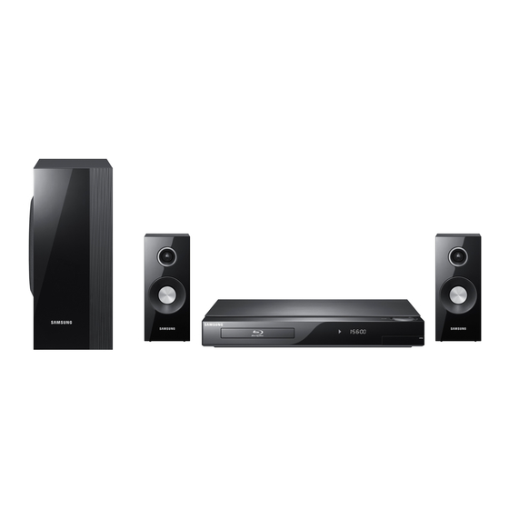
2.1CH Blu-ray Home Theater System
HT-C5200
Refer to the service manual in the GSPN (see the rear cover) for the more information.
2.1CH Blu-ray
Home Theater System
Model Name : HT-C5200
Model Code : HT-C5200/EDC
Speaker
PS-C5200
Front
PS-FC5200
Subwoofer
PS-WC5200
Manual
1. Precaution
2. Product Specification
3. Disassembly & Reassembly
4. Troubleshooting
5. Exploded View & Part List
6. PCB Diagram
7. Schematic Diagram
CONTENTS
Advertisement
Table of Contents

Related Manuals for Samsung PS-FC5200


Summarization of Contents
Service Manual: 2.1CH Blu-ray Home Theater System
1. Precaution
General safety guidelines and warnings for service.
2. Product Specification
Details product features, technical specifications, and analysis.
3. Disassembly & Reassembly
Step-by-step instructions for disassembling and reassembling the unit.
4. Troubleshooting
Guidance for diagnosing and resolving common error modes.
1. Precaution
1-1 Safety Precautions
Essential safety rules to follow during servicing and operation.
1-2 Servicing Precautions
Specific safety measures for technicians performing repairs.
1-3 Precautions for Electrostatically Sensitive Devices (ESDs)
Procedures to prevent damage to sensitive electronic components.
2. Product Specification
2-1 Product Feature
Lists key features and capabilities of the HT-C5200 system.
2-2 Specifications
Provides technical data including weight, dimensions, and performance.
2-4 Accessories
2-4-1 Supplied Accessories
Details the items provided with the product, like cables and manuals.
3. Disassembly & Reassembly
3-1 Overall Disassembly & Reassembly
Instructions for the general disassembly and reassembly of the main unit.
4. Troubleshooting
4-1 Checkpoints by Error Mode
Diagnostic flowcharts for various operational errors and symptoms.
4.2 Initialization & Upgrade Methods
4-2-1 How to check F/W version
Steps to access and display the current firmware version information.
4.3 Buyer-Region Code Setting Method
4-3-1 Inserting Region Code after replacing the Main PBA
Procedure to input the region code after main board replacement.
5. Exploded View & Part List
5-1 Product Exploded View
Diagram showing the assembly of the main product components.
Part List
List of all parts used in the product, with part numbers and descriptions.
5-4 Electrical Part List
Detailed list of all electrical components and their specifications.
6. PCB Diagram
6-1 Wiring Diagram
Schematic showing interconnections between different PCBs and connectors.
6-2 FRONT PCB Top
Component layout and pin connections for the front PCB.
6-3 KEY PCB Top
Component layout and pin connections for the key input PCB.
6-4 AMP PCB Top
Component layout and pin connections for the amplifier PCB.
6-6 MAIN PCB Top
Component layout and pin connections for the main PCB.
6-8 SMPS PCB Top
Component layout and pin connections for the SMPS PCB.
7. Schematic Diagram
7-1 Overall Block Diagram
High-level overview of signal flow and component interaction.
7-2 FRONT
Schematic for the front panel interface circuitry.
7-8 ETHERNET / USB / WI-FI
Schematic for connectivity interfaces: Ethernet, USB, and Wi-Fi.
7-10 HDMI MICOM
Schematic for HDMI interface controlling MICOM operations.
7-13 NAND FLASH / CLOCK / BBS / JTAG
Schematic for memory interfaces and debug connections.
7-16 7630 POWER / DECOUPLING
Schematic showing power supply and decoupling components.
7-22 DC-DC POWER
Schematic illustrating the DC-DC power conversion circuits.
7-24 SMPS
Schematic for the Switched Mode Power Supply (SMPS) unit.
Need help?
Do you have a question about the PS-FC5200 and is the answer not in the manual?
Questions and answers