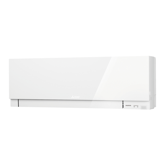
Advertisement
Table of Contents
INDOOR UNIT
SERVICE MANUAL
Models
MSZ-EF18VEW/B/S
MSZ-EF35VEW/B/S
MSZ-EF18VE2W/B/S
MSZ-EF35VE2W/B/S
MSZ-EF18VE2W/B/S
MSZ-EF35VE2W/B/S
MSZ-EF18VE3W/B/S
MSZ-EF35VE3W/B/S
MSZ-EF35VE3W/B/S
MSZ-EF∙VEW
MSZ-EF∙VEB
MSZ-EF∙VES
MSZ-EF22VEW/B/S
-
E1
MSZ-EF42VEW/B/S
-
E1
MSZ-EF22VE2W/B/S
-
E1
MSZ-EF42VE2W/B/S
-
E1
MSZ-EF22VE2W/B/S
-
ER1
MSZ-EF42VE2W/B/S
-
ER1
MSZ-EF22VE3W/B/S
-
,
E1
E2
MSZ-EF42VE3W/B/S
-
,
E1
E2
MSZ-EF22VE3W/B/S
MSZ-EF42VE3W/B/S
-
,
ER1
ER2
Outdoor unit service manual
MUZ-EF∙VE(H) Series (OBH590)
MXZ-C∙VA Series (OB584)
Revision G:
• 5. OUTLINES AND DIMENTIONS has been
modified.
• Some descriptions have been modified.
OBH589 REVISED EDITION-F is void.
MSZ-EF25VEW/B/S
-
E1
MSZ-EF50VEW/B/S
-
E1
MSZ-EF25VE2W/B/S
-
E1
MSZ-EF50VE2W/B/S
-
E1
MSZ-EF25VE2W/B/S
-
ER1
MSZ-EF50VE2W/B/S
-
ER1
MSZ-EF25VE3W/B/S
-
,
E1
E2
MSZ-EF50VE3W/B/S
-
,
E1
E2
MSZ-EF25VE3W/B/S
-
,
ER1
ER2
MSZ-EF50VE3W/B/S
-
,
ER1
ER2
MXZ-D∙VA Series (OBH626)
MXZ-8B Series (OCH480)
CONTENTS
1. TECHNICAL CHANGES ······························3
2. PART NAMES AND FUNCTIONS ··················6
3. SPECIFICATION ········································9
4. NOISE CRITERIA CURVES ························ 11
5. OUTLINES AND DIMENSIONS ··················· 13
6. WIRING DIAGRAM ··································· 16
7. REFRIGERANT SYSTEM DIAGRAM ··········· 18
8. SERVICE FUNCTIONS ······························ 19
9. MICROPROCESSOR CONTROL ················ 21
10. TROUBLESHOOTING ······························· 29
11. DISASSEMBLY INSTRUCTIONS ················· 43
PARTS CATALOG (OBB589)
1
No. OBH589
REVISED EDITION-G
-
E1
-
E1
-
E1
-
E1
-
ER1
-
ER1
-
E1
-
E1
-
ER1
-
ER1
,
E2
,
E2
,
ER2
,
ER2
Advertisement
Table of Contents

Summarization of Contents
Part Names and Functions
Accessories
Lists and illustrates various included accessories for the indoor unit.
Service Functions
8-1. Timer Short Mode
Shortens the set time for ON/OFF timers and compressor start-up.
8-2. PC Board Modification for Individual Operation
Modifies PC boards to allow individual operation of multiple indoor units.
8-3. Set Remote Controller Exclusively
Assigns a specific remote controller to an individual indoor unit.
8-4. Auto Restart Function
Enables the unit to restart in the previous mode after power interruption.
Microprocessor Control
Wireless Remote Controller
Details the functions and layout of the wireless remote controller.
Indoor Unit Display Section
Explains the operation indicator lamp and its states.
Operating Modes
Covers COOL, DRY, FAN, HEAT, and AUTO modes.
Auto Vane Operation
Details the automatic control and adjustments of the horizontal vane.
Timer Operations
Explains how to set and use timer functions, including weekly timers.
Special Operations
Covers i-save, emergency/test, and time delay operations.
Troubleshooting
10-1. Cautions on Troubleshooting
Provides essential safety precautions before performing troubleshooting.
10-2. Failure Mode Recall Function
Describes how to recall and interpret error codes from the unit's memory.
10-3. Instruction of Troubleshooting
Presents a flowchart for diagnosing operational issues and potential causes.
10-4. Troubleshooting Check Table
Lists common abnormal points, symptoms, conditions, and remedies.
10-5. Trouble Criterion of Main Parts
Provides methods to check the functionality of key internal components.
Specific Troubleshooting Flows
Detailed guides for diagnosing issues with fan motor, PC boards, wiring, and noise.
10-7. Test Point Diagram and Voltage
Provides diagrams of test points and expected voltage readings for diagnosis.
Disassembly Instructions
1. Removing the Panel
Step-by-step guide for safely removing the unit's front panel.
2. Remove the Indoor Electrical Box
Instructions for detaching the indoor electrical box.
3. Removing Major P.C. Boards
Guides for removing power, control, display, and receiver boards.
4. Removing the Nozzle Assembly
Instructions for detaching the nozzle assembly and related components.
5. Removing the Horizontal Vane Motor
Steps to remove the horizontal vane motor unit.
6. Removing Fan, Thermistor, and Line Flow Fan
Guides for removing the indoor fan motor, thermistors, and line flow fan.


Need help?
Do you have a question about the MXZ-8B Series and is the answer not in the manual?
Questions and answers