
Related Manuals for HIPOTRONICS OC60-DI


Summary of Contents for HIPOTRONICS OC60-DI
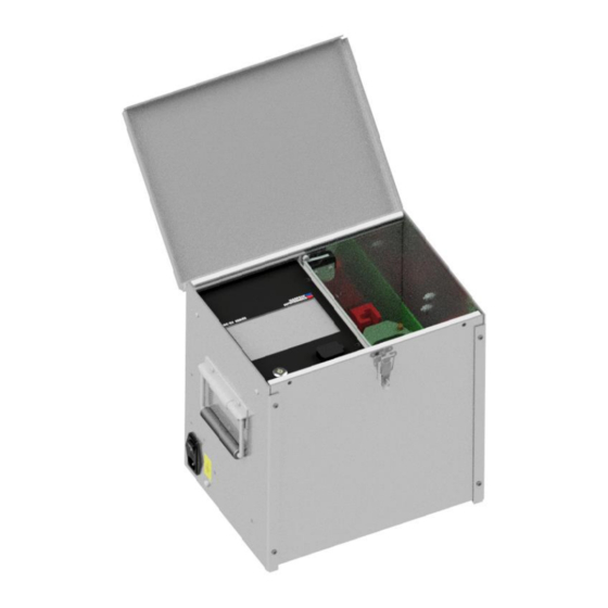
- Page 1 Operating Instructions OC-DI Series Digital Interface Oil Testers Version 1.0 No. 145896...
- Page 2 Title Digital Interface Oil Testers Date 06/2018 Revision History V0.1 03/2018 Initial draft of the document...
- Page 3 Note HIPOTRONICS has a policy of continuing improvement on all their products. The design of this instrument will be subject to review and modification over its life. There may be small discrepancies between the manual and the operation of the instrument, particularly where software has been upgraded in the field.
-
Page 4: Manual Conventions
Manual Conventions In the manual, the following conventions are used: Indicates hazards. There is a risk of equipment damage or personal injury or death. Carefully read and follow the instructions. Be sure to follow any safety instructions given in addition to those for the site at which tests are being performed. - Page 5 Foreword Welcome, new user of the “OC-DI Series”. Thank you for placing your confidence in our product. With the purchase of this measuring instrument you have opted for all the advantages that have built a world-wide reputation for a HIPOTRONICS Instrument: robustness, performance and quality.
-
Page 6: Table Of Contents
Contents Manual Conventions Introduction Receiving Instructions .................. 8 General ......................8 Scope of Supply ................... 8 1.2.1 Standard Scope of Supply ............... 8 Technical Data: OC60-DI ................9 1.3.1 Physical and Environmental Specifications ........9 1.3.2 Measurement .................. 9 Safety General ...................... - Page 7 Instrument Storage ..................23 Packing and Transport ................24 Recycling ....................24 Customer Support Appendix Declaration of Conformity................26 Hipotronics, Inc..................26 Warranty ....................27 Returned Material (RMA) ......Error! Bookmark not defined.
-
Page 8: Introduction
A suitable remark should be recorded on the delivery documents. A claim for damage must be reported immediately to the transport company and to the Customer Support Department of HIPOTRONICS or the local agent. It is essential to retain the damaged packing material until the claim has been settled. -
Page 9: Technical Data: Oc60-Di
Technical Data: OC60-DI 1.3.1 Physical and Environmental Specifications 14…122° F (-10 .. 50°C) Operating temperature -4…158° F (-20 .. 70°C) Storage temperature Humidity 5 ... 95 % r.h. non-condensing OC60-DI: 16” x 13” x 15” (41cm x 33cm x 38cm) Dimensions (W x D x H) Weight OC60-DI: 60lbs (25kg) -
Page 10: Safety
The unit should only be operated after carefully reading the user manual, which is an integral part of the instrument. HIPOTRONICS and its sales partners refuse to accept any responsibility for consequential or direct damage to persons and/or goods due to none observance of instructions contained herein or due to incorrect use of the equipment. -
Page 11: Summary
Never operate the equipment in an explosive environment or where there are flammable gases or fumes The instrument must always be connected to a grounded power outlet (i.e. a safety earth). It must never be operated in a non-grounded configuration as this may result in electrical shock to the user or damage to the instrument. -
Page 12: Theory
3 Theory Introduction This model is designed to meet testing specifications from all parts of the world with test cells available for ASTM D877, ASTM D1816 and IEC 156 testing standards. The OC60-DI offers the ability to use one of the pre-programmed rates of voltage rise or allows the operator to create their own tests using Basic mode. -
Page 13: Oil Tester Ports
4 Oil Tester Ports Ports LCD Touchscreen Interface: Use to control software to setup and implement oil tests Mains Input: Insert power cord to power or recharge unit. When charging, make sure that the input switch is in the ‘ON’ position Ground Terminal: Connect chassis to proper ground Power Button: Turn on/off unit interface. -
Page 14: Connection And Setup
5 Connection and Setup Ground Connections First make sure to connect the unit to a proper ground through the ground screw located on the left side of the oil tester. Prepare Oil Test Make sure the oil cup is properly cleaned twice before each oil sample test to ensure accurate results. -
Page 15: Main Menu
6 Operating Modes Main Menu Upon turning the unit on, the interface will load to the Main Menu window. The top bar is the status indicator at all times. It will be green when high voltage is off, and red when high voltage is on. The left corner of the bar will display what window is currently displayed. -
Page 16: Basic Mode
Basic Mode Although Basic Mode is the simple automatic ramping oil test, the user now has the ability to set many different parameters and options to make the test as easy and hands-free as possible. If testing to a common industry standard, the user can select the clipboard icon to view a list of pre-loaded standards that will automatically populate all of the parameter fields for that test. - Page 17 After pressing the ‘START’ button, the chosen test sequence will commence, and a new window will show all of the test parameters. The high voltage will ramp up to the selected target voltage, at the selected ramp rate, and then remain at that voltage for the chosen dwell time. Once the dwell time expires, or a breakdown occurs, the test will shut off high voltage and wait for the selected wait- time before starting a next ramp test, (if they were multiple number of tests selected).
-
Page 18: Multi-Step Mode
Multi-Step Mode In Multi-Step mode, each test has the capability to customize multiple ramping sequences for unique testing scenarios. By clicking on the cells in the table, the user can select the ramp rate, target voltage, and dwell time for each sequence in the test. To add a step in the test sequence, click the ‘plus- sign cell’... - Page 19 During a test sequence, the left side of the screen will display similar information to Basic Mode (see Section 5.3 for detailed information). The right side of the screen will display all of the breakdowns for the test cycle, and the current step in the sequence. At the start of the test, the voltage will ramp up to the first step’s target voltage, at the selected ramp rate, and then dwell at that voltage for the selected dwell time.
-
Page 20: Reports
Reports In the Reports window, all of the previously saved test data will be in a report labelled by its date and time of test. Use the touchscreen to select a report to view. When viewing a report on the unit, several of the chosen test parameters will be displayed, along with the calculated average breakdown voltage, standard deviation of the breakdowns, the breakdown range, and a graph of the breakdowns. -
Page 21: Settings
Settings Under the Settings window, there are two tabs to adjust the default test parameters, or the system’s settings. The user can either choose to default load the system presets when the unit is turned on, or use the parameters from the most recently performed test. The adjustable system parameters include the internal memory’s date/time, the touchscreen brightness, and the displayed language. -
Page 22: Troubleshooting
7 Troubleshooting Diagnostics Warning and Error Messages “Low Battery Please The internal battery is low and needs to be recharged via AC Recharge the battery” Mains. Unit is still able to be operated while charging without any adverse effects. “Lid Open” While the lid cover is not over the high voltage chamber, the test will not continue and high voltage is prevented to be present. -
Page 23: Miscellaneous
8 Miscellaneous Care and Maintenance The Oil Tester instrument is basically service free, as long as the specified environmental conditions are adhered to. As a result, service and maintenance is restricted to cleaning of the equipment and calibration at intervals stipulated by the application for which the instrument is used. 8.0.1 Cleaning the Instrument The instrument should be cleaned with a lint free cloth, slightly moistened using mild household cleanser, alcohol or spirits. -
Page 24: Packing And Transport
Packing and Transport DO NOT SHIP THE UNIT WITH THE OIL TEST CELL INSIDE! The packing of the oil tester instrument provides satisfactory protection for normal transport conditions. Nevertheless, care should be taken when transporting the instrument. If return of the instrument is necessary, and the original packing crate is no longer available, then packing of an equivalent standard or better should be used. -
Page 25: Customer Support
All error messages appear on the display of the oil tester measuring instrument. If persistent problems or faulty operation should occur then please contact the Customer Support Department of HIPOTRONICS or your local agent. The Customer Support Department can be reached at the following address:... -
Page 26: Appendix
Appendix Declaration of Conformity Hipotronics, Inc. 1650 Route 22 North PO Box 414 Brewster, NY 10509 Declared, under his own responsibility, that the below mentioned product complies with the requirements of the listed standards or other normative documents. So, the product complies with the requirements of the EMC directive 2004/108/EC and the low voltage directive 2006/95/EC. -
Page 27: Warranty
Hipotronics, Inc. is liable, the Purchaser agrees to reimburse Hipotronics, Inc. for all expense incurred. Upon receipt of the defective part or material, or after access to same, Hipotronics, Inc. shall inspect the part or material to determine the validity of Purchaser's claim.
Need help?
Do you have a question about the OC60-DI and is the answer not in the manual?
Questions and answers