Table of Contents
Advertisement
Advertisement
Table of Contents

Subscribe to Our Youtube Channel
Related Manuals for HIPOTRONICS 800PL Series


Summary of Contents for HIPOTRONICS 800PL Series
- Page 1 Operating Instructions 840PL-HD 800PL Series DC HIPOT Testers Version 1.3...
- Page 2 Title 40kV DC Hipot High-Duty-Cycle Date 01/2020 Authors MC, MW, RO Layout Part number 840PL-HD Revision History V0.1 06/2019 Initial draft of the document V1.0 01/2020 Released Version V1.1 4/2020 Changed operation software screenshots to new version V1.2 10/2020 Updated Specifications Page V1.3 3/2023 Added HIPODirect Section...
- Page 3 Note HIPOTRONICS has a policy of continuing improvement on all their products. The design of this instrument will be subject to review and modification over its life. There may be small discrepancies between the manual and the operation of the instrument, particularly where software has been upgraded in the field.
- Page 4 Manual Conventions In the manual, the following conventions are used: Indicates a matter of note. If it refers to a sequence of operations, failure to follow the instructions could result in errors in measurement. Indicates hazards. There is a risk of equipment damage or personal injury or death. Carefully read and follow the instructions.
- Page 5 With the purchase of this measuring instrument you have opted for all the advantages that have built a world-wide reputation for a HIPOTRONICS instrument: robustness, performance and quality. As a result, this instrument provides a solution which achieves the optimal combination of traditional know-how and leading edge technology.
-
Page 6: Table Of Contents
Contents Introduction Receiving Instructions .................. 4 General ......................4 Scope of Supply ................... 4 1.2.1 Standard Scope of Supply ............... 4 Technical Data: 840PL-HD ................5 1.3.1 General Specifications ..............5 1.3.2 Model Specifications ............... 5 Safety General ......................6 Essential Safety Recommendations ............ - Page 7 Instrument Storage ..................31 Packing and Transport ................31 Recycling ....................31 Customer Support Declaration of Conformity................33 Hipotronics, Inc......................33 Warranty ....................34 Introduction...
-
Page 8: Introduction
A suitable remark should be recorded on the delivery documents. A claim for damage must be reported immediately to the transport company and to the Customer Support Department of HIPOTRONICS or the local agent. It is essential to retain the damaged packing material until the claim has been settled. -
Page 9: Technical Data: 840Pl-Hd
1.3 Technical Data: 840PL-HD 1.3.1 General Specifications Power Input 90 – 264VAC 50/60Hz Operating Temperature 14 … 122°F (-10 … 50°C) Storage Temperature -4 … 158°F (-20 … 70°C) Humidity 5 … 95% R.H. non-condensing ECCN # 3A992.A HTS US Code 9030.39.0100 1.3.2 Model Specifications Model #... -
Page 10: Safety
The unit should only be operated after carefully reading the user manual which is an integral part of the instrument. HIPOTRONICS and its sales partners refuse to accept any responsibility for consequential or direct damage to persons and/or goods due to none observance of instructions contained herein or due to incorrect use of the equipment. -
Page 11: Essential Safety Recommendations
2.1 Essential Safety Recommendations Before connecting the instrument ensure that the device-to-be tested is completely de-energized and isolated from both line and load. Every terminal should be checked and verified before connection of the instrument. Ground connections may be left in place. Never operate the equipment in an explosive environment or where there are flammable gases or fumes The instrument must always be grounded (i.e. -
Page 12: Theory
3 Theory 3.0 Introduction The 840PL-HD has a user tested and approved digital 7” color touchscreen display and now boasts a longer duty cycle with no voltage restrictions other than the maximum output. Users can now program hipot test sequences in automatic mode or simply control the test voltage using manual mode. It is also equipped with data acquisition software for exporting test results via USB 2.0. -
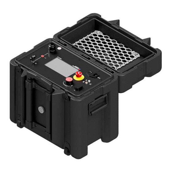
Page 13: 840Pl-Hd Front Panel
4 840PL-HD Front Panel 4.0 Interface Points-of-Interest 6 – On/Off Power Switch 1– High Voltage Output 7 – AC Power Input 2– HV Return Input 8 – Warning Strobe Beacon Input 3– Earth Ground Connection 9 – External Interlock Input 4–... -
Page 14: Glossary Of Front Panel Symbols
4.1 Glossary of Front Panel Symbols Symbol Meaning Symbol Meaning Protective Earth Safety Beacon Port Ground Push-to-Click Ground Rotary Knob Guard Return Interlock External Interlock The External Interlock input allows for an external interlock or "deadman" switch which will prevent High Voltage from turning on unless the interlock switch is closed. - Page 15 Accessories The following accessories are available for the 800PL-DC Part Number Description Image HH-FS Foot-Operated Interlock Switch HH-SAFE Safety Strobe Light with Magnetic Base HHDA13-280 Grounding Stick with 25ft braided lead, rated to 120kV 840PL-HD Front Panel...
-
Page 16: Connection And Setup
5 Connection and Setup 5.0 Ground Connections First, make sure to connect a ground cable from the 840PL-HD ground stud to a nearby earth-ground point. The ground stud for the 840PL-HD is located on the bottom left corner of the front panel(as indicated in the previous section). - Page 17 Single Phase Cable: Grounded Multi-Conductor Cable (Individual Concentric Neutrals/Shields): Connection and Setup...
- Page 18 Grounded Multi-Conductor Cable (Single Conductive Neutral/Shield): Connection and Setup...
-
Page 19: Internal Switch Between Ground And Guard (Ust)
5.1.2 INTERNAL SWITCH BETWEEN GROUND AND GUARD (UST) The sole function of this mode of operation is to separate the paths of leakage currents. These leakage currents are leakage to ground and leakage across the test specimen. The leakage currents to GROUND are bypassed around the current meter, measuring only the specimen leakage current. - Page 20 Vacuum Bottle Special Safety Instructions Follow these safety procedures upon completion of testing. Turn Off Procedure Warning!! Never press the HIGH VOLTAGE OFF pushbutton or turn off the main power switch immediately upon completion of a high voltage test. When stored energy is greater than 1 kilojoule, allow the energy to bleed down until the voltmeter reading is zero.
- Page 21 When completing a dc insulation test of large capacitive loads, the following steps are recommended for the protection of both the user and the equipment. Note: upon completion of test, step 1 is automatically done for you. 1. Ramp voltage down to zero (0) and press STOP. (Note: current meter values may display as red-colored negatives;...
-
Page 22: Software User Interface
6 Software User Interface 6.0 Main Menu Upon booting up the unit, the screen will load to the Main Menu. You can select one of the two test modes, Automatic or Manual mode; or you can view previously saved Reports; or view/change any of the system Settings. -
Page 23: Test Modes
6.1 Test Modes Operation Interface with HV OFF – WiFi Connected Indicator 10 – Volt Meter Display, Touch to Toggle Analog/Digital – High Voltage Indicator 11 – Ungrounded-Specimen or Grounded-Specimen Selection – Emergency Stop Engaged 12 – Overcurrent, Touch to Set –... - Page 24 Note, HV ON/OFF Button will be grayed out until E-Stop is OFF, Interlock Circuit is CLOSED, Power input is connected, and the Amplifier turns on. 1. Before starting the test, confirm Ungrounded-Specimen-Test (UST) or Grounded- Specimen-Test (GST) Current Measurement Circuit option. If the test specimen’s return is ungrounded, select UST, and refer to section 5.1.2.
- Page 25 calculated automatically. Operating the Equipment AUTOMATIC Test with Analog Meter Display – Ramp Rate, select cell to edit 4 – Preset, select to load/view/save – Target Voltage, select cell to edit 5 – Add or Remove steps – Dwell Time, select cell to edit Setting up an Automatic Test 1.
- Page 26 4. Input Dwell Time (00:00 → 60:00 min) 5. Add/Remove additional steps in multi-step sequence 6. Confirm GST or UST mode 7. After all parameters are entered, Press HV ON to start High Voltage and begin Test The Test will end when the Target Voltage is reached and the Dwell Time reaches 0:00 or when the Max Leakage current limit is reached.
- Page 27 Note: When performing withstand tests on cable, Manual mode is recommended. At the conclusion of the test, ramp the voltage back down to Zero before pressing STOP. Software User Interface...
-
Page 28: Reports Test Reports
6.2 Reports Test Reports Accessing Test Reports Test reports can be accessed from the main menu by touching the ‘Reports’ button from the main menu Reports Menu Test reports are organized by time, with the most recent at the top. From this menu, the user can select a test report, scroll down, or return to the main menu. - Page 29 – Name of Saved Test Report, click to edit 4 – Return to Reports List – USB Drive Detected, if shown 5 – Voltage Display, press to toggle – Graph Legend 6 – Current Display, press to toggle 7 – Export Report to USB Drive, if detected 8 –...
- Page 30 Applications and Recommended Connections to Select Devices Under Test Insulation Resistance Measurement The 800PL series calculates Insulation Resistance (IR) during Automatic and Manual mode operation (See Page 9, Item 13). IR measurement range is 10 kΩ…40 GΩ Depending on the duration of the test the system will calculate the following: o Dielectric Absorption Ratio(DAR): ▪...
-
Page 31: Settings
6.3 Settings Calibration: To proceed to the Calibration menu, a prompt will appear for a passcode. Please contact Hipotronics for this information. Zero Meters: Tare the voltage and current meters. Please make sure nothing is connected to the output cable and return port when this button is pressed. -
Page 32: Hipodirect
6.4 HIPODirect HIPODirect is HIPOTRONICS software app solution to wirelessly connect a mobile device to WiFi-direct capable products. Once connected the software can show product details, as well as view and download test reports. Once downloaded, the test reports can be easily shared in CSV format via e-mail or by uploading them to any cloud service. -
Page 33: Troubleshooting
7 Troubleshooting ISSUE CAUSE SOLUTION Verify that input power is on. Verfiy power cord is connected to input source and 800PL-HD Unit does not power on No Input power Power switch is in the ON position. Check fuse ( 250VAC, 10A) Consult factory Use rotary knob (See page 3, note 12) to Touch screen disabled in... - Page 34 Test Mode Display Prompts MESSAGE CAUSE ACTION "Stop" button pressed. Rotary knob pressed Press "Start" button only once to initiate test. TEST STOPPED while "Stop" button is Press Rotary knob only once to initiate test. highlighted. System in self-protect Power off 800PL-HD, wait 2 minutes, and mode.
-
Page 35: Miscellaneous
An annual calibration of the instrument is recommended. As the calibration process is fairly extensive, the instrument is recommended to be calibrated annually and, if necessary, adjusted at HIPOTRONICS’s factory. An updated calibration report will then be issued. 8.1 Instrument Storage If the instrument is to remain unused for any length of time, it is recommended to protect this high precision instrument from moisture and accumulation of dust and dirt with a suitable covering. -
Page 36: Customer Support
9 Customer Support All error messages appear on the display of the 840PL-HD instrument. If persistent problems or faulty operation should occur then please contact the Customer Support Department of HIPOTRONICS or your local agent. The Customer Support Department can be reached at the following address:... -
Page 37: Declaration Of Conformity
9.0 Declaration of Conformity Hipotronics, Inc. 1650 Route 22 North PO Box 414 Brewster, NY 10509 Declared, under his own responsibility, that the below mentioned product complies with the requirements of the listed standards or other normative documents. So, the product complies with the requirements of the EMC directive 2004/108/EC and the low voltage directive 2006/95/EC. -
Page 38: Warranty
This Warranty shall not apply to any accessories, parts or materials not manufactured or supplied by Hipotronics, Inc. and if, in the sole discretion of Hipotronics, Inc., Purchaser's claim relates to any materials of a component part, or of the manufacturer of a device of which the defective part is a component, Hipotronics, Inc.
Need help?
Do you have a question about the 800PL Series and is the answer not in the manual?
Questions and answers