
Related Manuals for YASKAWA SIEMENS YS 840DI

Summarization of Contents
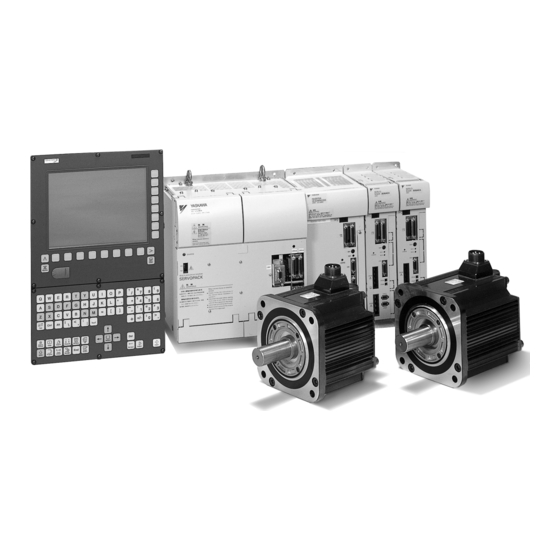
Chapter 1 System Configuration
1.1 System configuration
Overview of system configuration, including wiring and components.
1.2 Meanings of component designations
Explains the structure and meaning of designations for SERVOPACKs, servo motors, and spindle motors.
Chapter 2 Installing the control panels
2.1 Designing the panels
Guidelines for designing control panel enclosures, including environmental and thermal considerations.
2.2 Protecting against electric noise
Methods for preventing electric noise interference, focusing on cable separation and noise-proofing devices.
2.3 Installation precautions
Important precautions for installing CNC units, SERVOPACKs, and I/O modules within enclosures.
Chapter 3 Installing the motors
3.1 Servo motors
Environmental requirements and installation guidelines for SGMKS-type servo motors.
3.2 Spindle motors
Recommendations for installing spindle motors, focusing on cooling, rigidity, and site cleanliness.
Chapter 4 Connection method
4.1 Arrangement of connectors and switches
Details connector and switch arrangements on the CNC unit, power supply, I/O modules, converters, and inverters.
4.2 Power on/off signals
Explains wiring procedures for servo power-on, brake release signals, and UPS module timer settings.
4.3 Wiring units and devices
Covers PROFIBUS-DP address/termination settings and rotary switch configuration for inverters and servo units.
Chapter 5 Assembling and replacing
5.1 Installing the CNC unit
Step-by-step instructions for installing the CNC unit (PCU50), including component assembly and board insertion.
5.2 Replacing the servo unit fan
Procedures for replacing cooling fan units in various kW servo units, with attention to airflow direction.
5.3 Installing the servo unit optional board
Instructions for installing optional boards onto servo units, detailing cover removal and board securing steps.
Chapter 6 Software configuration
6.1 System software components
Lists system software components for HMI, NC, PLC, Servo unit, Inverter, and Converter with versions.
6.2 Data types
Describes the various data types handled by the YS 840DI system and their storage locations.
Chapter 7 Backup
7.1 How to archive
Procedure for backing up programs and data individually, including target screen and archive name entry.
7.2 Network settings
Instructions for configuring network settings on YS 840DI and target PC for data transfer.
Chapter 8 General programming notes
8.1 LAD/FBD/STL compatibility
Explains the compatibility and convertibility between PLC programming languages like LAD, FBD, and STL.
8.3 Address structure
Details the address structure for bits, bytes, timers, and counters in STEP7 programming.
Chapter 9 SIMATIC manager and hardware configuration
9.1 Hardware configuration
Explains configuring PLC modules and setting parameters using the SIMATIC manager hardware configuration screen.
9.2 Defining the hardware
Steps for defining hardware configuration: creating projects, adding stations, racks, and modules.
9.3 Uploading hardware configuration
Describes methods for uploading hardware configuration information from a CPU to a project using two different methods.
Chapter 10 Overview of System
10.1 Screen operation
Explains the YS 840DI screen system, including basic concepts and operation procedures.
10.2 MD components
Illustrates the drive-related Machine Data (MD) and their relationships within the YS 840DI system.
Chapter 11 Drive Parameter Screen
11.1 Drive Parameter Screen Operation
Details how to indicate and edit drive parameters, including startup, screen configuration, and operation methods.
11.2 Drive Diagnosis Function
Explains the drive diagnosis function for checking parameter read/write status and initiating diagnosis.
11.4 Error screen display and troubleshooting
Provides information on error screen displays, troubleshooting steps, and error message lists.
Chapter 12 How to use Digital Operation
12.1 Basic operation
Explains basic operations of the digital operator, including connecting, key functions, and mode switching.
12.2 Application
Details application operations of the digital operator for adjusting motor functions, checking types, and managing settings.
Chapter 13 Drive system overview 1
13.1 System configuration
Provides an overview of the YS 840DI drive system configuration and its main features.
13.2 Specification of machine data and parameters
Explains the structure of machine data (CNC data) and parameters (Drive data) in the YS 840DI system.
Chapter 14 Drive set-up procedure
14.1 Fundamental settings
Covers essential fundamental settings for axis control, including control cycles, NCK processing, and encoder setup.
14.2 Servo control
Details servo control parameters like position, speed, and torque control, including various compensation functions.
14.3 Motion Control
Explains motion control functions such as feed rate, acceleration/deceleration, positioning, and emergency stop.
14.4 High-speed High-accuracy Cutting
Discusses functions for high-speed cutting, including block compression and spline interpolation.
Chapter 15 Error and Troubleshooting
15.1 Errors without Alarm Display and Troubleshooting
Provides a summary of common malfunctions without alarm generation and their countermeasures for servo motors.
Chapter 16 Maintenance and Check
16.1 Checking Servo motor and SERVOPACK
Outlines daily checks and annual maintenance procedures for servo motors and SERVOPACKs.
16.2 Checking Spindle motors and Invertors
Details scheduled maintenance and daily checks for spindle motors and inverters, including Megger tests.
16.3 Absolute encoder
Covers procedures for replacing the battery and setting up (initializing) the absolute encoder using a digital operator.
16.4 Analogue monitor
Explains monitoring various signals via analog voltage and configuring monitor settings using user constants.
Appendix A Parameters
A.1 Servo unit parameter list
A comprehensive list of servo unit parameters, including CNC and drive parameter numbers, and settings.
A.2 List of Servo unit parameter switches
Details the settings and descriptions for servo unit parameter switches used for function selection.
A.3 List of Inverter parameter
A list of inverter parameters, including CNC/drive numbers, typical values, units, and descriptions.
A.4 List of parameters common to all drives
Lists parameters common to Servo units and Inverters, used for CNC interface and data display.
Appendix B Alarm/monitor data
B.1 List of Servo unit alarms
A reference list of servo unit alarms, correlating CNC and drive codes with descriptions.
B.2 List of Inverter alarms
A reference list of inverter alarms, correlating CNC and drive codes with descriptions.
B.3 List of Servo unit monitor data
Lists monitor data for servo units, including UN numbers, items, descriptions, and units.
B.4 List of Inverter monitor data
Lists monitor data for inverter units, including UN numbers, items, descriptions, and units.
Need help?
Do you have a question about the YS 840DI and is the answer not in the manual?
Questions and answers